Emergi-Lite Preceptor Remote Capacity Series User Manual
Important safeguards, Read and follow all safety instructions, Save these
Emergi-Lite
Tel: (888) 552-6467 ext. 547 or 255
Fax: (888) 867-1565
www.emergi-lite.com
07/04 750.1099 Rev. A
Preceptor Series – Remote Load Die Cast EXIT Series
1/4
Preceptor Series – Remote Load Die Cast EXIT Series
IMPORTANT SAFEGUARDS
When using electrical equipment, basic safety precautions should
always be followed including the following:
READ AND FOLLOW ALL SAFETY
INSTRUCTIONS
1. Do not use outdoors.
2. Do not let power supply cords touch hot surfaces.
3. Do not mount near gas or electric heaters.
4. Use caution when handling batteries. Avoid possible shorting.
5. Equipment should be mounted in locations and at heights where it
will not readily be subjected to tampering by unauthorized personnel.
6. The use of accessory equipment not recommended by the manufac-
turer may cause an unsafe condition.
7. Caution: If optional Halogen cycle lamp(s), symbol (H—), are used in
this equipment, to avoid shattering: do not operate lamp in excess of
rated voltage, protect lamp against abrasion and scratches and
against liquids when lamp is operating, dispose of lamp with care.
8. Halogen cycle lamps operate at high temperatures. Do not store or
place flammable materials near lamp.
9. Do not use this equipment for other than intended use.
10. All servicing should be performed by qualified service personnel.
SAVE THESE
INSTRUCTIONS
Installation Instructions
1. Turn off unswitched AC power.
2. Route unswitched AC wires into the junction box and leave 12” of
wire length.
3. Remove canopy assembly from carton. Remove canopy backplate
from canopy and retain securement screws.
4. Remove proper knockouts in canopy backplate (including the center
knockout) to mount to the wall. Route unswitched AC wires through
center hole in canopy backplate. Mount canopy backplate to the elec-
trical box using the existing screws.
Note — For wall mounted signs, make sure that the screw holes on
the canopy backplate are facing down - this will ensure that the test
switch and pilot light face downwards.
5. Disconnect male half of the AC connector (located in the canopy, see
fig. 2) from AC wire harness and make the proper connections. Our
unit accepts an input voltage of 120 VAC or 277 VAC (see fig. 5).
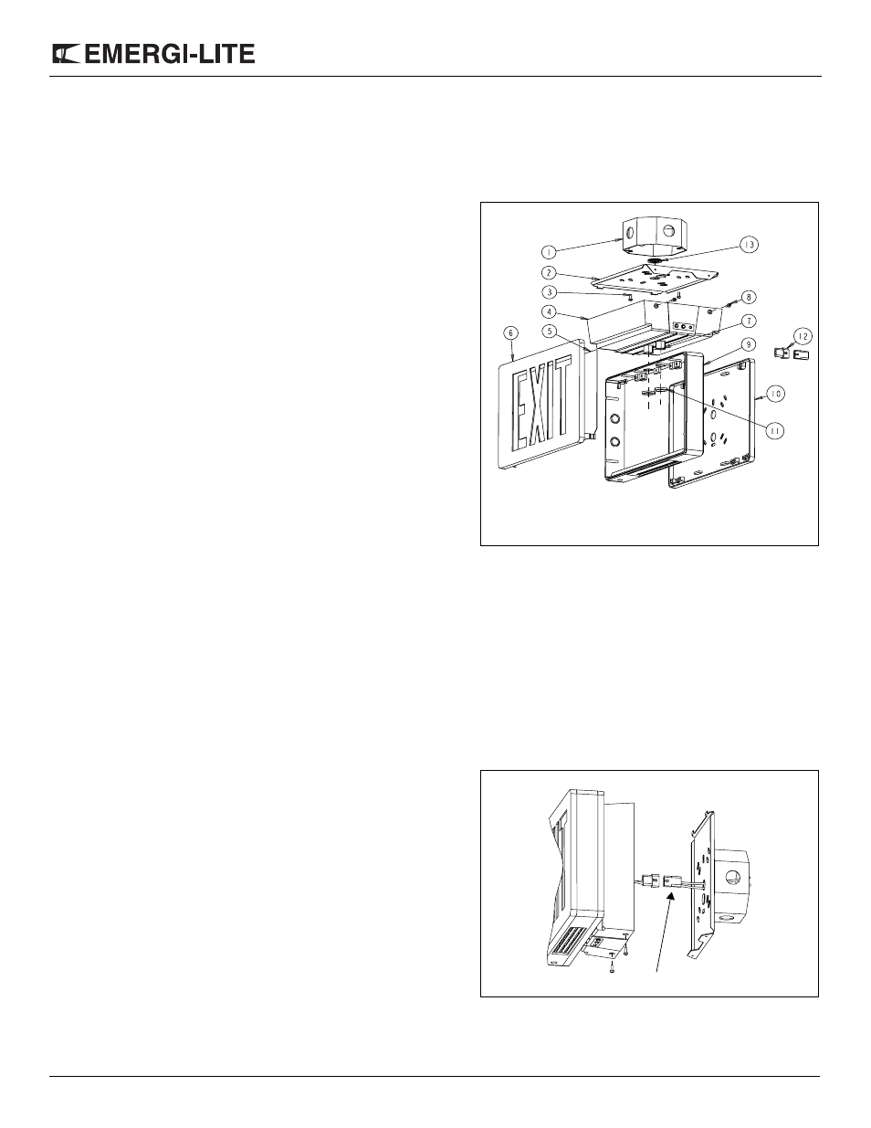
Figure 1
1. Junction box (not supplied)
2. Canopy backplate
3. Junction box screws (not
supplied)
4. Canopy
5. Colored diffuser (one for
single sided units and two
for double sided units)
6. Exit door
7. Hex. nipple (2)
8. Securement screws (2)
9. Exit frame
10. Exit back (or second exit
door for double faced units)
11. Hexagonal nuts (2)
12. AC connector
13. Bushing
Part List
Figure 2
AC connector