Emergi-Lite Survive-All SV Series User Manual
Important safeguards, Read and follow all safety instructions, Save these instructions
Emergi-Lite
Tel: (888) 552-6467
Fax: (800) 316-4515
www.emergi-lite.com
10/13 750.1518 Rev. B
1/4
SV Series – Survive-All
SV Series – Survive-All
Emergency Light unit
IMPORTANT SAFEGUARDS
When using electrical equipment, basic safety precautions should
always be followed including the following:
READ AND FOLLOW ALL SAFETY
INSTRUCTIONS
1.
All servicing should be performed by qualified service personnel.
2.
Do not let power supply cords touch hot surfaces.
3.
Do not mount near gas or electric heaters.
4.
Use caution when handling batteries. Avoid possible shorting.
5.
Equipment should be mounted in locations and at heights where it
will not readily be subjected to tampering by unauthorized personnel.
6.
The use of accessory equipment not recommended by the
manufacturer may cause an unsafe condition.
7.
Caution: If optional Halogen cycle lamp(s), symbol (H—), are used in
this equipment, to avoid shattering: do not operate lamp in excess of
rated voltage, protect lamp against abrasion and scratches and
against liquids when lamp is operating, dispose of lamp with care.
8.
Halogen cycle lamps operate at high temperatures. Do not store or
place flammable materials near lamp.
9.
Do not use this equipment for other than intended use.
SAVE THESE INSTRUCTIONS
Installation Instructions
1. Turn off unswitched AC power.
2. Open clear cover by removing the screws making sure not to loose
the screw gaskets. Remove lamp protectors.
3. Remove the electronic module. Pull on the cover until snapping fea-
tures disengage or use a screw driver by inserting it into the slots
shown in figure 12 and prying the cover open.
4. Remove the battery in order to access the knockouts (k’out).
5. Install back plate:
Wall mounting on a junction (figure 2)
a. Route unswitched AC circuit wires into the junction box and leave
6” of wire length.
b. Remove the k’outs needed to mount back plate. Considering the
weight of the unit, it’s recommended to use key hole for additional
securing(see fig.4). For Nexus wired option, install the liquidtight
fitting, provided with the unit. Use the k’out located on the bottom
of the unit.
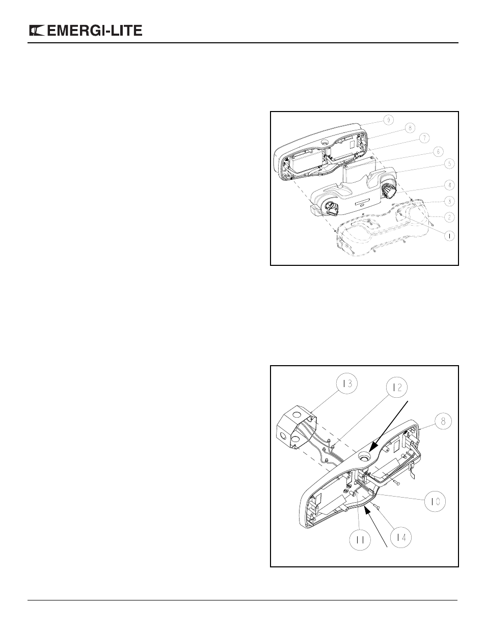
Figure 1
Part List
1.
Tamper-proof screws (6)
2.
Clear cover
3.
Screw gasket
4.
Lamps
5.
Electronic module
6.
Battery
7.
Battery strap or bracket
8.
Backplate
9.
Gasket
10. AC harness
11. Ground wire
12. Wire nut
13. J-box (not supplied)
14. J-box screws (not supplied)
15. Screw cover
Figure 2
knockout
for conduit
knockout for
Nexus data cables