Emergi-Lite Premier Series Thermoplastic Combination Battery Unit and Exit Sign User Manual
Important safeguards, Read and follow all safety instructions, Save these
Emergi-Lite
Tel: (888) 552-6467
Fax: (800) 316-4515
www.emergi-lite.com
03/10 750.1401 Rev. C
Premier Series - Thermoplastic LED Combo Sign
1/2
Premier Series - Thermoplastic LED Combo Sign
Self-Powered LED model
IMPORTANT SAFEGUARDS
When using electrical equipment, basic safety precautions should always be taken
including the following:
READ AND FOLLOW ALL SAFETY
INSTRUCTIONS
1. Do not use outdoors.
2. Do not let power supply cords touch hot surfaces.
3. Do not mount near gas or electric heaters.
4. Equipment should be mounted in locations and at heights where it will not
readily be subjected to tampering by unauthorized personnel.
5. The use of accessory equipment not recommended by the manufacturer may
cause an unsafe condition.
6. Do not use this equipment for other than intended use.
7. All servicing should be performed by qualified service personnel.
SAVE THESE
INSTRUCTIONS
Installation Instructions
1. Turn off AC power.
2. Route AC unswitched circuit of rated voltage into electrical box and leave 6” of
wire length.
3. Remove face plate screws (only for some models). Remove the combo front
door using a coin or a screwdriver at the top or bottom of the door. Arrows on
the frame point towards the front door (See Fig. 2).
4. Determine the mounting position (wall or ceiling). Note: a canopy(6) is required
for ceiling mount.
5. Our system can accept input voltages of 120 VAC, 277 VAC. Therefore, con-
nect the black (120 VAC) or orange (277 VAC) and white (common) leads to
the building utility. Connect the green wire to the ground. Unused primary wire
must be insulated to prevent shorting.
Wall mounting
No canopy required. Remove the battery(s) with wires. With the help of flat
head screwdriver, knock out the proper hole pattern on the back cover,
including the center hole, to mount to a standard junction box as well as
the two wall anchoring points (See Fig. 2). Install means to anchor unit in
line with “Wall anchoring points”. Feed the AC supply leads (and DC leads
for remote lamps if applicable) around inside the housing, through the
plastic conduit and out through the center hole and make the proper con-
nections (See Fig. 6). Feed the excess wire into the junction box. Secure
the back plate to the wall at wall anchoring points using wall mount
screws(16), then to the junction box using the junction box screws(7). Pro-
ceed to step 6.
Conduit entry mounting
Remove knock-out for the conduit entry located on the top of the central
housing (See Fig. 2).
Secure unit to the wall following "Wall mounting" instructions and make
appropriate connections.
Ceiling mount
Canopy required. Remove the battery(s) with wires connected. Attach the
spider plate to electrical box with the junction box screws(7). Remove the
Insert tool and
push here to
remove lens
Figure 3
Figure 4
Detail A
Notches to Receive
Ribs on Canopy
Flat Head Screwdriver
Knock-out
Arrows Indicating Location
of Front Door
Groove
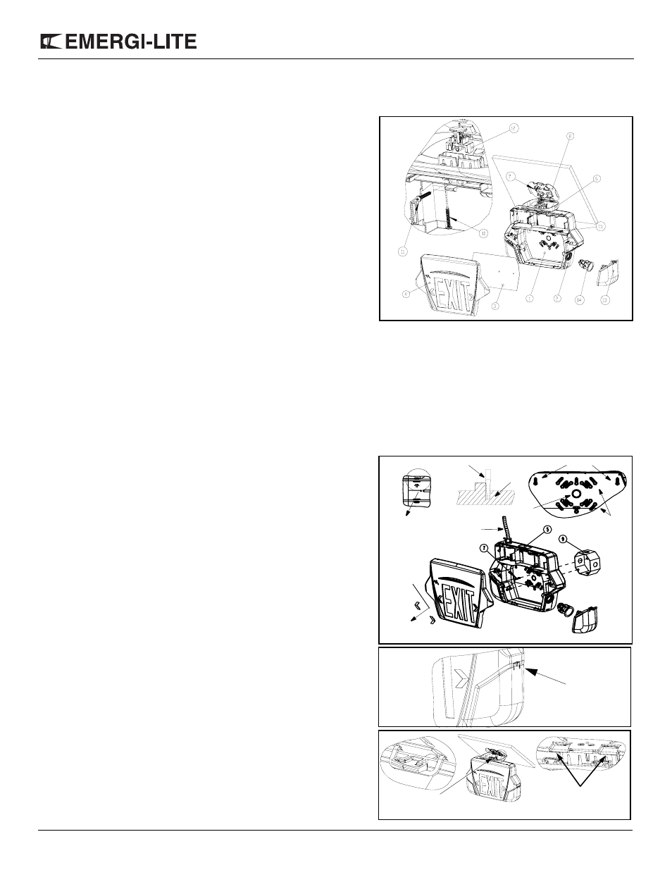
Figure 2
Figure 1
Wall Anchoring Points
Junction Box
Anchoring Points
Center Hole
Part List
1.
Back Plate
2.
Central Housing
3.
Diffuser Panel
4.
Face Plate
5.
Hole Plug for Canopy
6.
Canopy
7.
Junction Box Screws (not
Provided)
8.
Spider Plate
9.
Junction Box
10. Canopy Plate Screw
11. Canopy Housing Screw
12. Canopy Lock
13. Lens
14. Lamp Assembly
15. PCB
16. Wall Mount screws (not Pro-
vided)
Conduit
Chevrons
are pushed
outwards