Emergi-Lite Prestige DX Series User Manual
Important safeguards, Read and follow all safety instructions, Save these
Emergi-Lite
Tel: (888) 552-6467 ext. 547 or 255
Fax: (888) 867-1565
www.emergi-lite.com
04/07 750.0895 Rev.C
Prestige DX & DXN - Die Cast Aluminum LED Exit Series
1/3
Prestige DX & DXN - Die Cast Aluminum LED Exit Series
AC, AC/DC, Self-Powered and Nexus
IMPORTANT SAFEGUARDS
When using electrical equipment, basic safety precautions should
always be followed including the following:
READ AND FOLLOW ALL SAFETY
INSTRUCTIONS
1. Do not use outdoors.
2. Do not let power supply cords touch hot surfaces.
3. Do not mount near gas or electric heaters.
4. Equipment should be mounted in locations and at heights where it
will not readily be subjected to tampering by unauthorized personnel.
5. The use of accessory equipment not recommended by the manufac-
turer may cause an unsafe condition.
6. Do not use this equipment for other than intended use.
7. All servicing should be performed by qualified service personnel.
SAVE THESE
INSTRUCTIONS
Installation Instructions
1. Turn off AC unswitched power.
2. Route AC unswitched circuit of rated voltage into electrical box and
leave 6” of wire length.
3. Separate the housing assembly, back cover and exit door, using a
screwdriver (see fig. 3).
Canopy mount
a. Separate the canopy plate from the canopy assembly and retain
the securement screw (see fig. 2).
b. Remove the proper knockout in the canopy plate for desired
mounting position.
c. Feed the AC unswitched wires through the large hole in the can-
opy plate. Use the junction box screws to secure the canopy plate
to the junction box. Ensure the location for securement screw is
accesible.
d. To knock out the chevrons, remove the diffuser panel. Support
the door around the chevrons with two blocks of wood. Strike
arrow knockouts from the inside with a hammer and screwdriver.
Re-install the diffuser panel using the securement clips (see fig.
3).
e. Determine which side of the exit frame will be used for mounting.
Break out the appropriate rectangular section at the canopy
mounting position (see fig. 3). Make sure edges are free from
burrs.
f. Secure the canopy to the exit housing by guiding flange on the
canopy into the rectangular hole in the side (or top) of the hous-
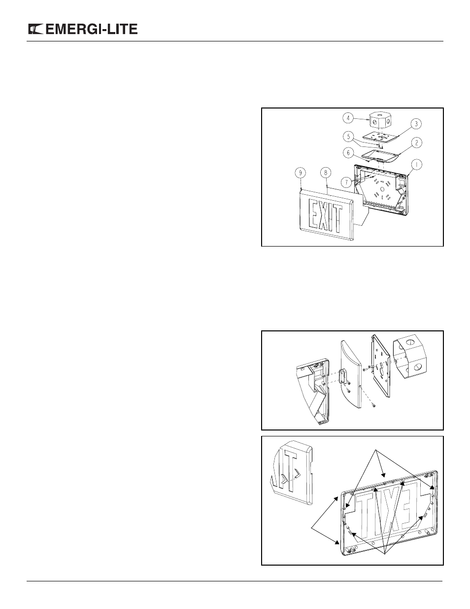
Figure 1
Part List
1. Back cover
2. Canopy
3. Canopy plate
4. Junction box (not supplied)
5. Junction box screws (not
supplied)
6. Securement screw
7. Canopy screws
8. Diffuser Panel
9. Exit door
Figure 2
Figure 3
Break out positions
Screwdriver slot
Securement clips