Emergi-Lite Survive-All SVX-HZ Series User Manual
Important safeguards, Read and follow all safety instructions, Save these instructions
Emergi-Lite
Tel: (888) 552-6467 ext. 547 or 255
Fax: (888) 867-1565
www.emergi-lite.com
06/07 750.1300 Rev. A
1/4
SVXHZ Series – Exit Sign
SVXHZ Series – Exit Sign
AC/DC & Self-Powered Models
IMPORTANT SAFEGUARDS
When using electrical equipment, basic safety precautions should
always be followed including the following:
READ AND FOLLOW ALL SAFETY
INSTRUCTIONS
1. Do not let power supply cords touch hot surfaces.
2. Do not mount near gas or electric heaters.
3. Use caution when handling batteries. Avoid possible shorting.
4. Equipment should be mounted in locations and at heights where it
will not readily be subjected to tampering by unauthorized personnel.
5. The use of accessory equipment not recommended by the manufac-
turer may cause an unsafe condition.
6. Do not use this equipment for other than intended use.
7. All servicing should be performed by qualified service personnel.
SAVE THESE INSTRUCTIONS
Installation Instructions
1. Turn off unswitched AC power.
Ceiling Mount
a. Remove j-box assembly from carton. Remove j-box cover from j-
box assembly and retain securement screw.
b. Install junction box and route unswitched AC circuit wires into the
junction box and leave 6” of wire length.
c. Remove lens, exit panel and diffuser panel on the front of the unit
(use the supplied bit to remove the tamper-proof screws).
d. In order to access the knockouts of the frame, remove the 4 elec-
tronic module screw(s) holding the electronic module to the frame
and separate them (see fig.2).
e. Remove knockout on top of the frame. Determine which holes in
the exit frame will be used for mounting (see fig.1). Support frame
by two blocks of wood, maximum one inch apart. Strike knockouts
with a hammer and screwdriver. Clear holes of burrs to allow
proper assembly of nipple/wire assembly.
f.
Secure j-box cover to the frame using the provided nut.
g. Reassemble the electronic module inside the frame.
11
2
3
4
5
6
9
10
1
7
8
16
12
14
13
15
17
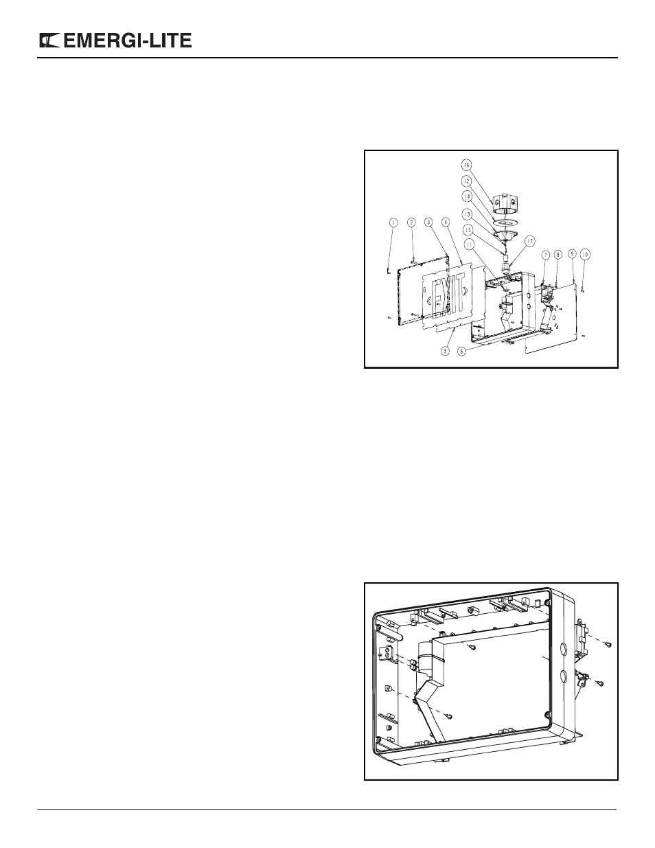
Figure 1
Part List
1.
Tamper-proof screws short
(4 per lens)
2.
Tamper-proof screws long
(2 per lens)
3.
Lens
4.
EXIT panel
5.
Diffuser panel
6.
Frame
7.
Electronic module
8.
Electronic module screws
(4)
9.
Backplate (single face sign)
10. Backplate tamper-proof
screws (4)
11. Lock-nuts (2)
12. Junction box gasket
13. Junction box screws(2)
14. J-box Cover
15. Nipple
16. Juction box
17. Hub
Figure 2