Svx series – survive-all combination unit, Manual testing, Automatic testing – Emergi-Lite Survive-All SVX Combo Series User Manual
Page 3: Automatic diagnostics
SVX Series – Survive-All Combination Unit
3/4
Emergi-Lite
Tel: (888) 552-6467 ext. 547 or 255
Fax: (888) 867-1565
www.emergi-lite.com
02/08 750.1157 Rev. B
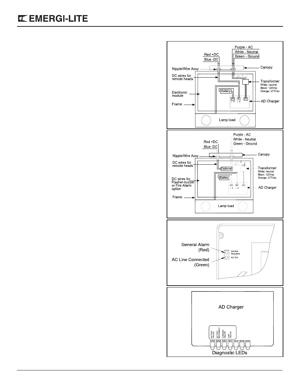
2. Electrical connections: Using the sealed AC nipple/wire assembly
(3 wires), connect one end to the transformer leads, inside the enclo-
sure, and the other end, to AC line voltage inside the junction box.
Connect the white lead to neutral and the green lead to ground. Con-
nect the purple lead to AC line voltage and to appropriate transformer
lead (See fig. 7 for color code).
Optional:
For models with DC remote capacity, the sealed DC nipple/wire
assembly (2 wires) will also need to be installed. One end connects
to the AD charger terminal block, inside the enclosure, and the other
end to DC output inside the junction box. Connect the red lead to
positive, and the blue lead to the negative of the remote DC output
(See fig. 7).
For models with flasher-buzzer or fire alarm, the sealed DC nipple/
wire assembly (2 wires) will also need to be installed. One end con-
nects to the optional module terminal block, inside the enclosure, and
the other end to DC input inside the junction box. Connect the red
lead to positive, and the blue lead to the negative (See fig. 8).
3. For canopy mount: Attach the canopy backplate to the junction box
using the junction box screws. Mount the frame and canopy assem-
bly to canopy back plate by using the provided securement screw.
4. For wall mount: Reinstall the electronic module inside the frame.
5. Reinstall the diffuser and the EXIT panel (if required, remove the
appropriate chevron).
6. Install the lens by using the 4 short and 2 long tamper-proof screws.
The tamper-proof screws should be equally torqued to approxi-
mately 5 lbs-in (0.6 N-m).
7. Remove the lamps protectors.
8. Energize AC. Sign will illuminate.
Manual Testing
Operate the magnetic “test switch” by holding the provided magnet near
the AC pilot lamp, where indicated on the legende. This will initiate a one
minute test. The DC lamps will illuminate for approximately one minute,
then the unit will automatically return to stand by mode. Test can be can-
celled by holding the magnet near the test switch again.
Automatic Testing
The unit will perform an automatic self-test of 1 minute every month,
30 minutes every 6 month and a 90 minutes self-test once a year.
Automatic Diagnostics
There are five diagnostic indicators: one external and four internal. Unit
must be opened to gain access to internal indicators.
External: General alarm, “Service Required”. The LED will turn-on if any
alarm condition is detected (see fig. 9).
Internal: Battery Failure, Battery Disconnect, Charger Failure & Lamp
Failure. Steady ON if alarm condition exists (See fig. 10).
Normal operation, No fault — “Service Required” is OFF.
Faulty operation — “Service Required” is ON.
(see AD charger owner manual for more details)
Figure 7
Figure 7
Figure 7
Figure 8
Figure 9
Figure 10