Retract-lite – emergency lighting, Lamp module installation (figure 8), Testing the equipment – Emergi-Lite Revelation Battery Series User Manual
Page 4
Retract-Lite – Emergency Lighting
4/4
Emergi-Lite
Tel: (888) 552-6467 ext. 547 or 255
Fax: (888) 867-1565
www.emergi-lite.com
01/08 750.1277 Rev. B
7. Place the two wires under the stopper bracket then slide the bracket
towards the left into the slot all the way in the back-box (Figure 8).
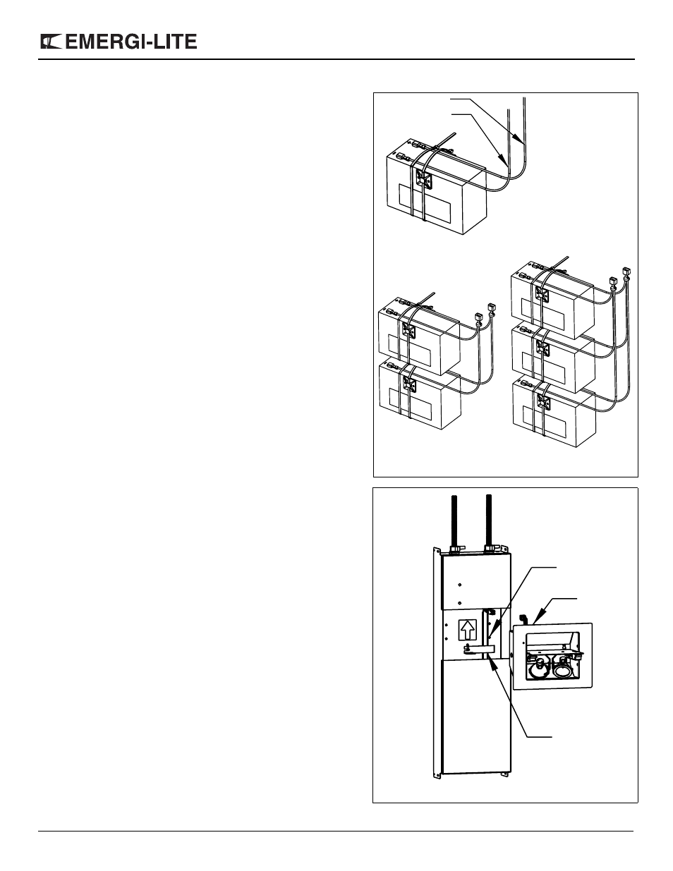
Three-battery module (Figure 7c)
1. Take the battery with the wiring harness attached. Verify if the wire
harness is well connected to the battery tab and tightly secured with
the tie-wrap.
2. Place the battery in the lower compartment of the back-box, with the
tabs to the left and the wire harness to the right side.
3. Take the second battery and run the wires with the female connectors
under the tie-wraps and connect them to the battery (RED to positive
and BLUE to negative).
4. Tighten the tie-wrap next to the battery terminals in order to secure
the wires in place.
5. Place this battery in the same direction as first battery.
6. Take the third battery and run the wires with the female connectors
under the tie-wraps and connect them to the battery (RED to positive
and BLUE to negative). Then follow the same instructions as in steps
4-5 above.
7. Connect the male connectors of the wiring harness to the RED and
BLUE wires from the charger module, as per the label indication
(RED wire to RED wire; BLUE wire to BLUE wire).
8. Place the two wires under the stopper bracket then slide the bracket
towards the left into the slot all the way in the back-box (Figure 8).
Lamp Module Installation (Figure 8)
1. Install the four screws (provided with the stopper bracket) 2-3 threads
into the pem-studs of the back-box.
2. Hold the lamp module by the harness and connect it to the 4-pin con-
nector of the charger module.
3. Push on one side of the door of the lamp module to open it half-way
and identify the four key holes in the housing.
4. Mount the lamp module by aligning it with the screws in the back-box.
Slide the lamp module so that the head of the screws are in the slot-
ted part of the key hole. (Make sure the harness and connector are
placed in the space provided between the back-box and the charger
module.)
5. Align the lamp module on the wall then secure it to the back-box by
tightening the four screws (located in the key holes) until its trim is
flush with the wall. (For easy access to the screws the door can be
rotated one ful turn of 360 degrees.)
6. Orient the two lamps in their swivels and verify that they are plugged
into the sockets.
7. Close the door and make sure that it is flush with the trim.
Testing the Equipment
1. Make the AC service.
2. The recessed pilot light/test switch will light in green.
3. Push the test button. The door will open and the lamps will illuminate
for one minute, then the door will close. Orient the lamps to the
desired position at this time. If more time is needed, push the test
button again.
4. The unit requires no maintence, but should be tested regulary in
accordance with the local codes.
Figure 7 a,b,c
Figure 7a
Figure 7b
Figure 7c
Red
Blue
From
charger
module
}
Stopper bracket
Lamp
Module
Figure 8
Mounting screws