Retract-lite – emergency lighting, Battery installation (figure 7a, b, c) – Emergi-Lite Revelation Battery Series User Manual
Page 3
Emergi-Lite
Tel: (888) 552-6467 ext. 547 or 255
Fax: (888) 867-1565
www.emergi-lite.com
Retract-Lite – Emergency Lighting
3/4
01/08 750.1277 Rev. B
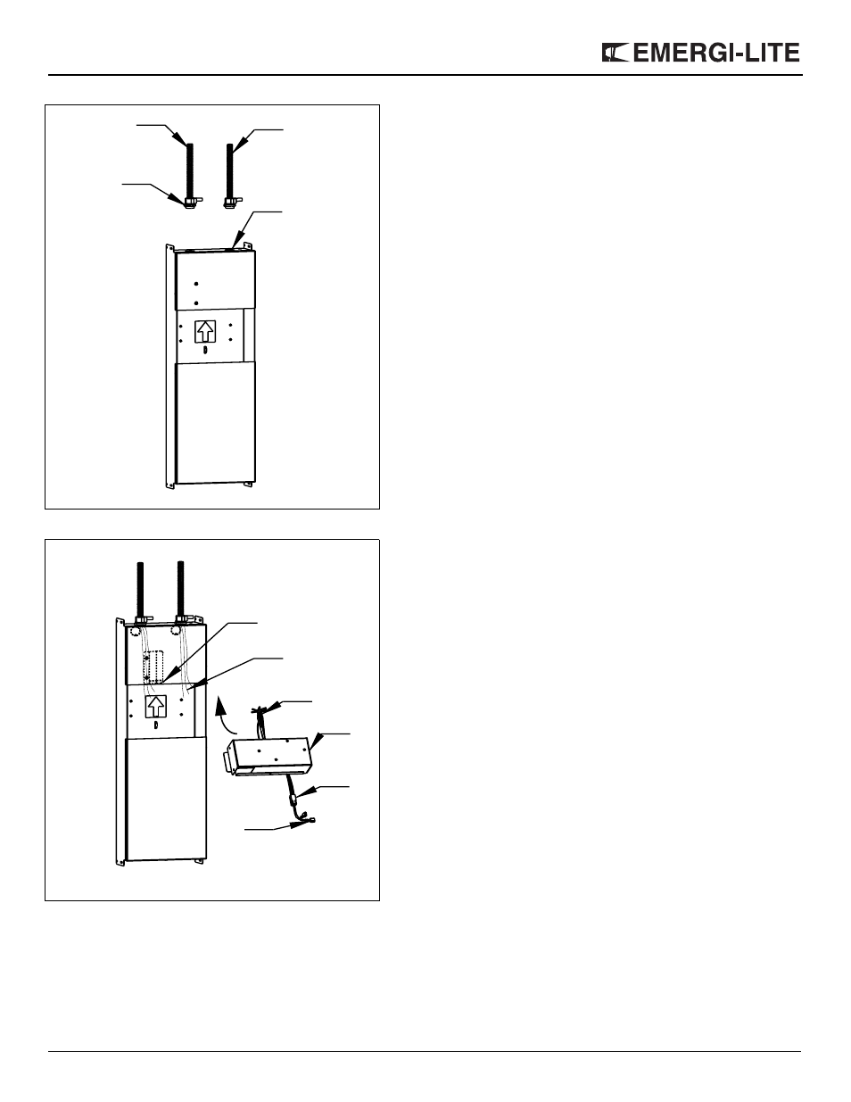
Charger Module Installation (Figure 6)
1. Pull out the electrical cables from the back box and cut the wires to
leave 2 to 3 inches of wire outside the back-box.
2. Connect the GREEN wires from the charger module and the back-
box to the GROUND supply wire.
3. For 120VAC connect the BLACK wire (labeled 120VAC) from the
charger module to Line and the WHITE wire (labeled neutral) to Neu-
tral.
4. For 277VAC connect the ORANGE wire (labeled 277VAC) from the
charger module to Line and the WHITE wire (labeled Neutral) to Neu-
tral.
5. For 347VAC connect the RED wire (labeled 347VAC) from the
charger module to Line and the WHITE (labeled Neutral) to Neutrall.
6. If there are any remote heads to be connected to the unit, connect
the RED wire (labeled L+) and the BLUE wire (labeled L-) to the load
out going wires.
7. Note: make sure all unused wires are capped
8. Caution: failure to cap the wires may cause an unsafe condition
9. Place the charger module in the back-box with the outcoming wires
on the right side. Enter the module at an angle, to bypass the flexi-
bale bracket in the back-box; then slide the module upward, until it is
latched by the flexible bracket. (Figure 6).
10. Check for secure installation.
Battery Installation (Figure 7a, b, c)
This equipment is provided with a battery module made up of one, twoor
three sealed batteries, depending on the rated capacity. Follow the
instructions below for the battery module configuration of your unit.
One-battery module (Figure 7a)
1. Take the 2 wires from the charger module (labeled: BATTERY CON-
NECTION) pass them under the tie-wraps and connect them to the
battery (RED to positive and BLUE to negative).
2. Tighten the tie-wrap next to the battery terminals in order to secure
the wires in place.
3. Place the battery in the lower compartment of the back-box, ensuring
that the battery terminals are facing the left and the wires on the right
side of the back box.
4. Place the two wires under the stopper bracket then slide the bracket
towards the left into the slot all the way in the back-box (Figure 8).
Two-battery module (Figure 7b)
1. Take the battery with the wiring harness attached. Verify if the wire
harness is well connected to the battery tab and tightly secured with
the tie-wrap.
2. Place the battery in the lower compartment of the back-box, with the
tabs to the left and the wire harness to the right side.
3. Take the second battery and run the wires with the female connectors
under the tie-wraps and connect them to the battery (RED to positive
and BLUE to negative).
4. Tighten the tie-wrap next to the battery terminals in order to secure
the wires in place.
5. Place the second battery in the same direction as first battery.
6. Connect the male connectors of the wiring harness to the RED and
BLUE wires from the charger module, as per the label indication
(RED wire to RED wire;BLUE wire to BLUE wire).
Figure 5
AC Supply
DC Supply
(If required)
Wall Mount
Knock Out
Conduit
Bushing
Figure 6
Upper
Compartment
Middle
Lower
Compartment
Compartment
To Charger
Module
To Incoming
Wires
Charger
Module
To Battery
To Lamp
Module
Flexible bracket