Teledyne IR-7000 - Non-dispersive infrared series User Manual
Page 36
Installation 3
IR7000
28
Teledyne Analytical Instruments., - Rev. 3
P
IN
#
F
UNCTION
P
IN
#
F
UNCTION
IN/OUT
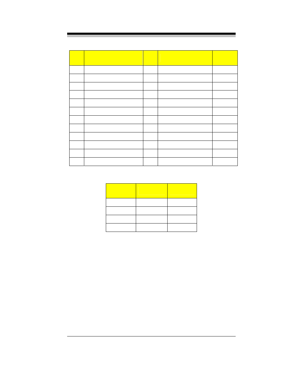
1
Range Bit 0 +
2
Range Bit 0 -
Output
3
Range Bit 1 +
4
Range Bit 1 -
Output
5
Doing Cal +
6
Doing Cal -
Output
7
Alarm/Limit 1 +
8
Alarm/Limit 1 -
Output
9
Alarm/Limit 2 +
10
Alarm/Limit 2 -
Output
11
Audible Alarm +
12
Audible Alarm -
Output
13 Spare1+
14 Spare1
-
Input
15
Spare2 +
16
Spare2 -
Input
17 Not
Used
18 Not
Used
19
Cal Req. Full/Zero +
20 Cal Req. Full/Zero -
Input
21
Cal Req. Span +
22
Cal Req. Span -
Input
23 Fault
+
24 Fault
-
Output
Table 3-2: Digital I/O Connector Pin Out
C
HART
R
ANGE
BIT
0
BIT
1
1 Off
Off
2 On
Off
3 Off On
4 On On
Table 3-3: Range ID Logic Table
Installation involves:
•
Fabricate the I/O cable with mating connector.
•
Mate cable and connector to the rear panel.
•
Connect opposite end(s) of cable to the input and output devices.
3.6.6 RS-232
Cable
An optional serial port is available for communication to and from a
remote computer. The port is a standard RS-232 serial communications
port and allows the user to input control functions and output data in
response to a variety of requests. A standard DB-9 male connector is
mounted on the rear panel for connection to a remote PC computer via a