Ndir gas analyzer installation 3, 6 electrical connections – Teledyne IR-7000 - Non-dispersive infrared series User Manual
Page 29
NDIR Gas Analyzer
Installation 3
Teledyne Analytical Instruments., - Rev. 3
21
WARNING: If your application uses a toxic, flammable or explosive gas, use
additional leak checking methods such as a hand held gas sniffer.
Periodically, use a portable combustible gas analyzer or sniffer
around all joints and fittings.
•
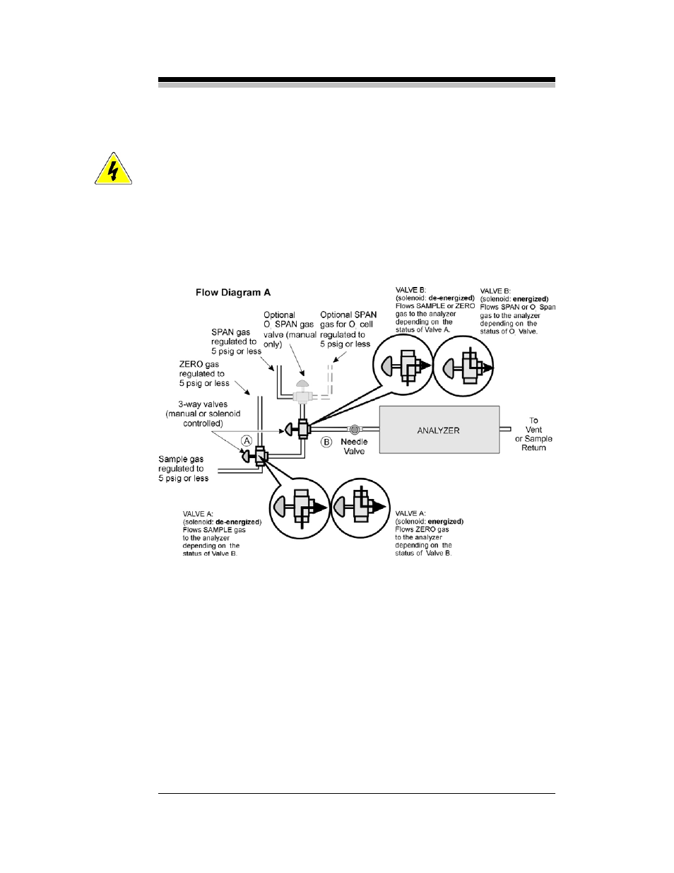
When there are no leaks in the sample system, run span gas
through and then sample gas to check the flow rates. If you are
using a bypass loop, do not set the sample or calibration
regulators above 5 psig in an effort to increase the flow.
3.6 Electrical
Connections
All electrical connections to the analyzer are made on the rear panel.
Figure 3-5 shows the rear panel for the IR7000 analyzer. Other models are
similar. Electrical connections to be made at the rear panel are:
•
Analog output
• O
2
channel output (optional)
•
2 solenoid valves (3 for explosion proof model)
•
4–20 mA current output (optional)
Figure 3-1: Suggested Sample System 1 (with Optional O
2
Cell )
- 1220 - Multipoint flammable gas and vapor detection system (50 pages)
- 212R - Thermal conductivity analyzer (28 pages)
- 235 - Thermal conductivity analyzer (38 pages)
- 275R - Portable turbine generator purge gas analyzer (21 pages)
- 2000A-EU - General purpose thermal conductivity analyzer (86 pages)
- 2000XTC - Thermal conductivity analyzer (40 pages)
- 2010A - Split architecture thermal conductivity analyzer (110 pages)
- 2010B - Split architecture thermal conductivity analyzer (98 pages)
- 2020 - Explosion proof thermal conductivity analyzer (80 pages)
- 2120 - Trace Nitrogen in Argon Analyzer (66 pages)
- 2120XL - Trace Nitrogen Analyzer (85 pages)
- 2230R - Process Hydrogen Analyzer (26 pages)
- 2240 – Portable Handheld Hydrogen Leak Detector, 3rd generation (updated 1/31/11) (30 pages)
- 2240 - Portable Handheld Hydrogen Leak Detector, 3rd generation (revision 2/29/08) (40 pages)
- 2240 – Portable Handheld Hydrogen Leak Detector, 2nd generation (13 pages)
- 2750 - Portable turbine generator gas analzyer (40 pages)
- 300P - Percent oxygen analyzer (24 pages)
- 306WA - Analog trace oxygen analyzer (46 pages)
- 311 - Portable trace oxygen analyzer (19 pages)
- 311D - Portable trace oxygen analyzer with digital meter (18 pages)
- 311XL - Portable trace oxygen analyzer (18 pages)
- 316RA / RB / RAD / RBD - Oxygen analyzers (24 pages)
- 319R - Oxygen analyzer (23 pages)
- 320 Series - Portable oxygen detectors (24 pages)
- 326, 327 and 328 - Oxygen analyzers (45 pages)
- 329R - Oxygen analyzer (22 pages)
- 335 - Analog control room monitor for personnel safety (24 pages)
- 356WA - Analog trace oxygen analyzer (42 pages)
- 3000MA - Paramagnetic oxygen analyzer (63 pages)
- 3000MA - Paramagnetic oxygen analyzer Addendum (2 pages)
- 3000MB - Paramagnetic oxygen analyzer (59 pages)
- 3000PA - General purpose percent oxygen analyzer (69 pages)
- 3000PAEU - General purpose percent oxygen analyzer (78 pages)
- 3000PB - Bulkhead mount percent oxygen analyzer (82 pages)
- 3000TA - General purpose trace oxygen analyzer (75 pages)
- 3000TA-EU - General purpose trace oxygen analyzer (89 pages)
- 3000TA-XLEU - Trace oxygen analyzer (108 pages)
- 3000TB - Bulkhead mount trace oxygen analyzer (78 pages)
- 3000TB-XL - Trace oxygen analyzer (78 pages)
- 3000ZA - Trace oxygen analyzer (81 pages)
- 3000ZA-3X - Trace oxygen analyzer (72 pages)
- 3000ZA2G - Zirconium oxide analyzer (72 pages)
- 3000 Ultra Trace - PPB oxygen analyzer (72 pages)
- 3010MA - Paramagnetic oxygen analyzer, includes 0-100% range (88 pages)
- 3010MA – Paramagnetic oxygen analyzer, no 0-100% range – (superceded) (88 pages)