Teledyne IR-7000 - Non-dispersive infrared series User Manual
Page 24
Operational Theory 2
IR7000
16
Teledyne Analytical Instruments., - Rev. 3
sample gas is to be returned to the process or flare, suitable back
pressure controls should be employed to ensure the analyzer vents
at a constant pressure.
2.5
Internal Gas Handling System
The gas handling system inside the analyzer is similar in principle for
all models. The following information describes the internal gas handling
system for the IR7000 model. Variations for other models will be noted.
Figure 2-4 is a diagram of the internal components and plumbing for
directing calibration or sample gas through the analyzer.
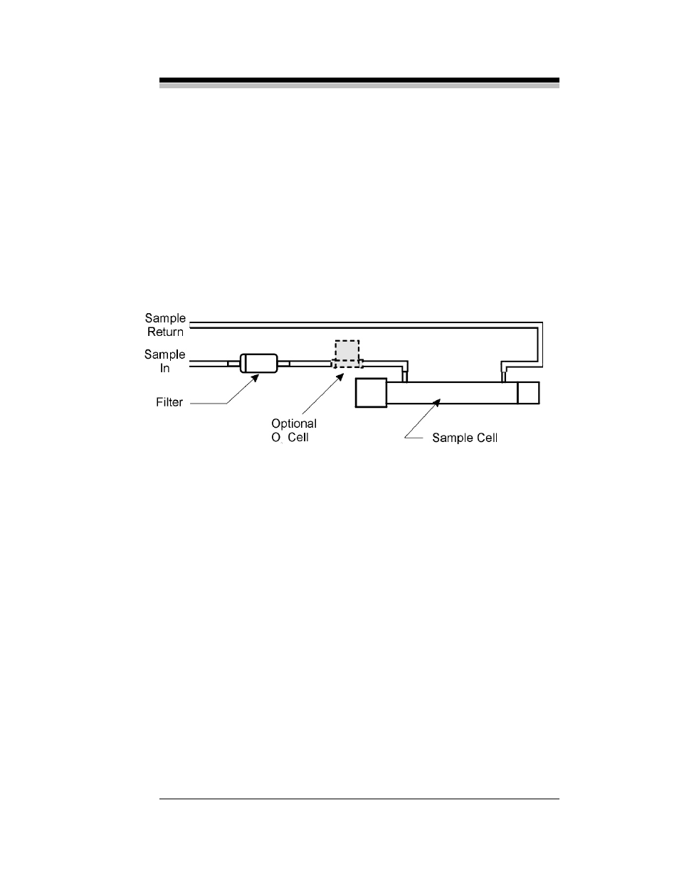
Figure 2-4: Sample Path Through Analyzer – Standard Model
Either sample or calibration gas is delivered under pressure to the
analyzer by the customer or LSC supplied sample system. The gas enters
the analyzer and passes through a 0.3-micron disposable filter to remove
any particulate matter. If an O
2
channel has been incorporated, the O
2
sensor is installed in series with the sample cell. The gas passes first
through the O
2
sensor and then through the sample cell and out to the
sample return.
In the portable model, a 12V DC mini-pump is installed between the
disposable filter and the sample cell. Otherwise the internal plumbing is
the same.
The internal gas handling systems installed in the split-architecture
and explosion proof models vary according to the specific application. In
general, the plumbing is the same as the standard models with the
following exceptions:
•
Metal tubing and fittings replace Teflon lined PVC tubing