Teledyne IR-7000 - Non-dispersive infrared series User Manual
Page 34
Installation 3
IR7000
26
Teledyne Analytical Instruments., - Rev. 3
NOTE:
The customer is responsible for supplying and installing the sample
system if one has not been provided by LSC. Liston cannot be
responsible for improperly designed or fabricated sample systems. If
questions arise regarding the suitability of a sample system or sample
system component, consult Customer Service for guidance.
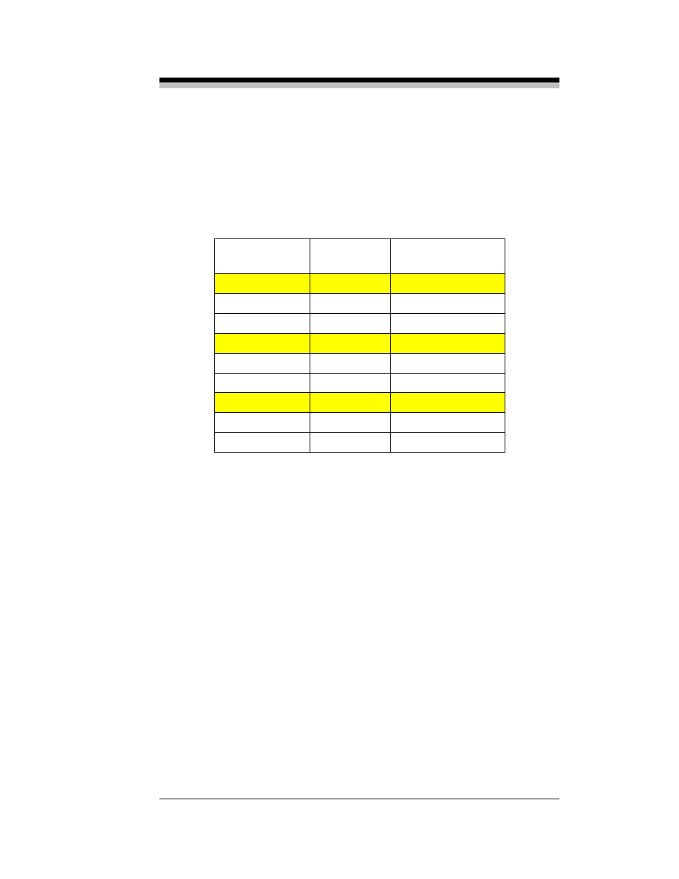
F
LOW
V
ALVE
S
OLENOID
S
TATUS
Zero Gas
A
energized
B
de-energized
Span Gas
A
de-energized
B
energized
Sample Gas
A
de-energized
B
de-energized
Table 3-1: Solenoid Status for Gas Flows
For the explosion proof and split-architecture models, provisions are
made for controlling 3 AC solenoid valves in the sample system. A similar
valve layout as shown in Figure 3-1 and 3-2 can be used for deploying 2
3-way valves for controlling calibration and sample gases. Alternatively,
one can used 3 2-way valves with a valve on each line (sample, zero and
span). See also the application shown in Figure 3-3.
Connections from the solenoid valves are made to the rear panel on
the control unit.
3.6.4 Optional Relay Outputs
AC / DC relays are available as an option on the IR7000 series of
analyzers. This option is not available for the portable model. If the
optional relays (K1, K2, K3) have been installed, the sets of connections
on the rear panel will be functional. Each relay is a single pole, double
throw relay and provides a common (C), normally closed (NC) and
normally open (NO) terminals for connection to the users equipment
(alarm lamps, annunciator, or other control, warning or recording devices.