Teledyne IR-7000 - Non-dispersive infrared series User Manual
Page 30
Installation 3
IR7000
22
Teledyne Analytical Instruments., - Rev. 3
•
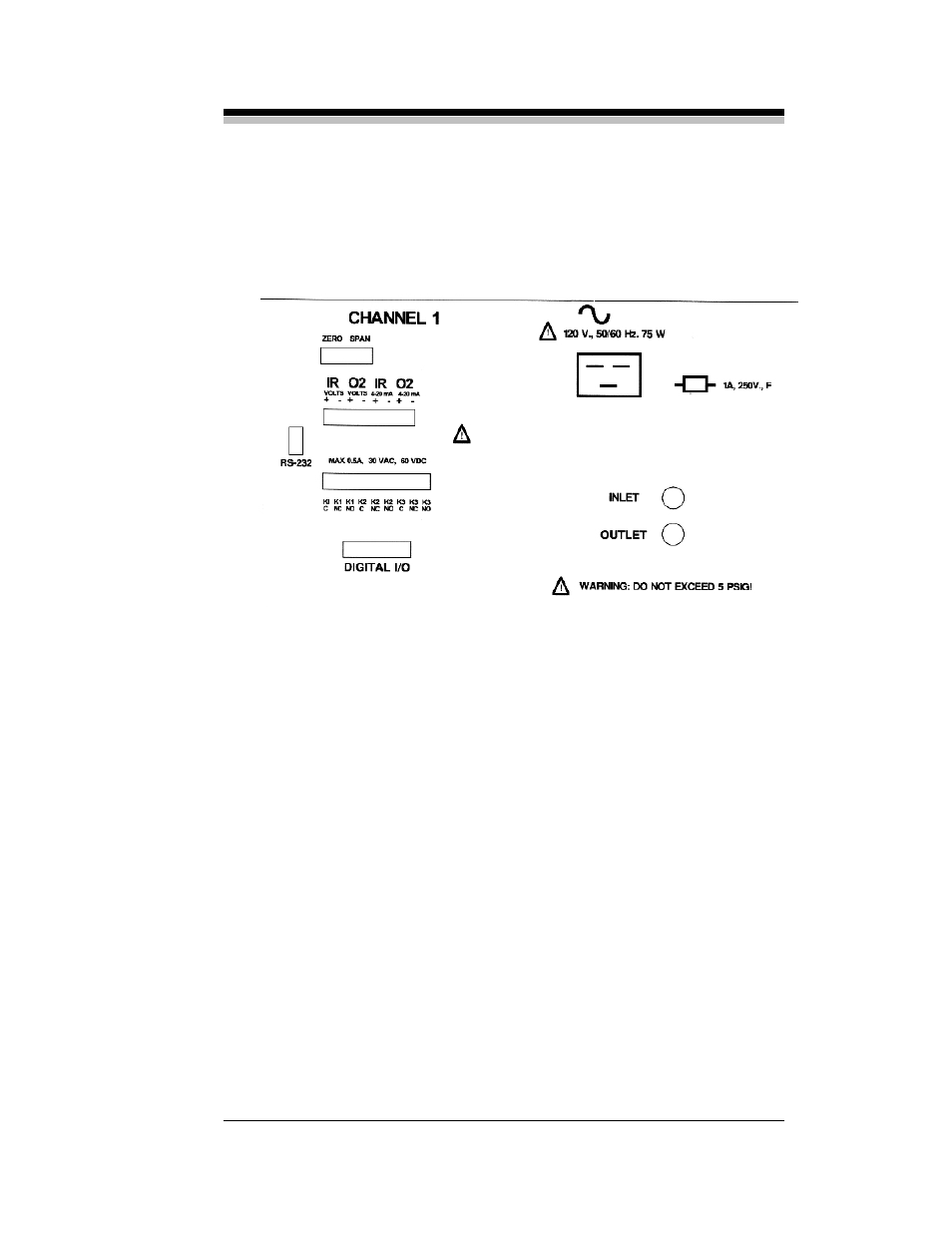
Relay outputs (optional)
•
Digital I/O (optional)
•
RS-232 Communications port
•
AC power connections
Figure 3-5: IR7000 Rear Panel
3.6.1 Analog
Output
The standard model IR7000 is equipped with a single set of analog
output terminals accessible from the rear panel. The output is set at the
factory to 0–1 VDC but can be changed to 0–5V or 0–10V full scale by
moving the slides on the switch labeled “S1” on the I/O board. The switch
is located at the upper edge of the I/O board as shown in Figure 3-6. Use
the table in the figure to set the slides for the desired output voltage. A 4–
20 mA isolated or non-isolated output is also available as an option.
A second set of 0–1, 0-5, or 0-10 VDC output terminals may be
driven if the optional O
2
monitoring channel is installed. If the instrument
is equipped with a dual bench, there will be 2 sets of terminals, one for
each bench.
- 1220 - Multipoint flammable gas and vapor detection system (50 pages)
- 212R - Thermal conductivity analyzer (28 pages)
- 235 - Thermal conductivity analyzer (38 pages)
- 275R - Portable turbine generator purge gas analyzer (21 pages)
- 2000A-EU - General purpose thermal conductivity analyzer (86 pages)
- 2000XTC - Thermal conductivity analyzer (40 pages)
- 2010A - Split architecture thermal conductivity analyzer (110 pages)
- 2010B - Split architecture thermal conductivity analyzer (98 pages)
- 2020 - Explosion proof thermal conductivity analyzer (80 pages)
- 2120 - Trace Nitrogen in Argon Analyzer (66 pages)
- 2120XL - Trace Nitrogen Analyzer (85 pages)
- 2230R - Process Hydrogen Analyzer (26 pages)
- 2240 – Portable Handheld Hydrogen Leak Detector, 3rd generation (updated 1/31/11) (30 pages)
- 2240 - Portable Handheld Hydrogen Leak Detector, 3rd generation (revision 2/29/08) (40 pages)
- 2240 – Portable Handheld Hydrogen Leak Detector, 2nd generation (13 pages)
- 2750 - Portable turbine generator gas analzyer (40 pages)
- 300P - Percent oxygen analyzer (24 pages)
- 306WA - Analog trace oxygen analyzer (46 pages)
- 311 - Portable trace oxygen analyzer (19 pages)
- 311D - Portable trace oxygen analyzer with digital meter (18 pages)
- 311XL - Portable trace oxygen analyzer (18 pages)
- 316RA / RB / RAD / RBD - Oxygen analyzers (24 pages)
- 319R - Oxygen analyzer (23 pages)
- 320 Series - Portable oxygen detectors (24 pages)
- 326, 327 and 328 - Oxygen analyzers (45 pages)
- 329R - Oxygen analyzer (22 pages)
- 335 - Analog control room monitor for personnel safety (24 pages)
- 356WA - Analog trace oxygen analyzer (42 pages)
- 3000MA - Paramagnetic oxygen analyzer (63 pages)
- 3000MA - Paramagnetic oxygen analyzer Addendum (2 pages)
- 3000MB - Paramagnetic oxygen analyzer (59 pages)
- 3000PA - General purpose percent oxygen analyzer (69 pages)
- 3000PAEU - General purpose percent oxygen analyzer (78 pages)
- 3000PB - Bulkhead mount percent oxygen analyzer (82 pages)
- 3000TA - General purpose trace oxygen analyzer (75 pages)
- 3000TA-EU - General purpose trace oxygen analyzer (89 pages)
- 3000TA-XLEU - Trace oxygen analyzer (108 pages)
- 3000TB - Bulkhead mount trace oxygen analyzer (78 pages)
- 3000TB-XL - Trace oxygen analyzer (78 pages)
- 3000ZA - Trace oxygen analyzer (81 pages)
- 3000ZA-3X - Trace oxygen analyzer (72 pages)
- 3000ZA2G - Zirconium oxide analyzer (72 pages)
- 3000 Ultra Trace - PPB oxygen analyzer (72 pages)
- 3010MA - Paramagnetic oxygen analyzer, includes 0-100% range (88 pages)
- 3010MA – Paramagnetic oxygen analyzer, no 0-100% range – (superceded) (88 pages)