Maintenance – Fulton Classic ICX or FB-F Vertical Tubeless Boilers (Steam) Oil Fired User Manual
Page 40
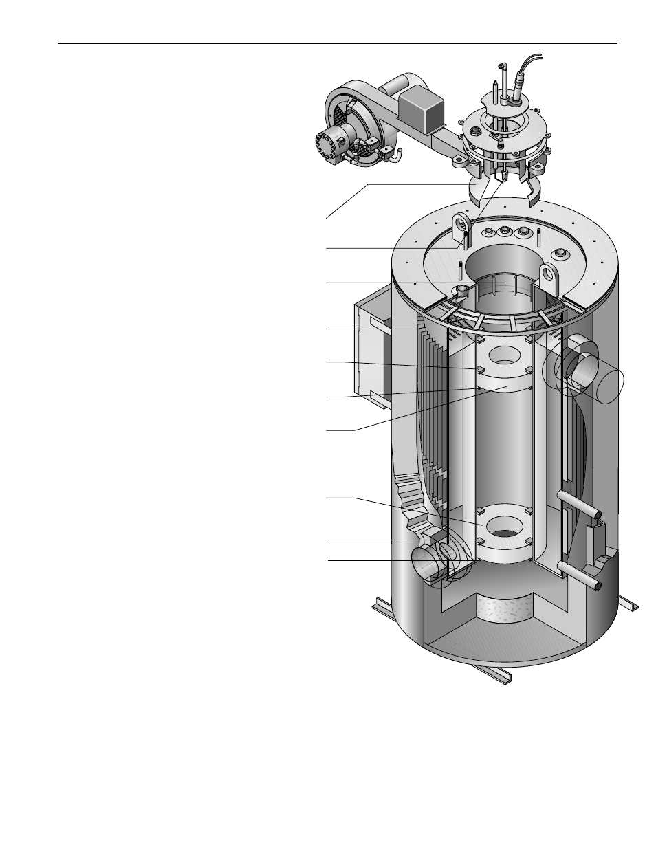
Furnace Refractory Replacement
Procedure
a) Remove the burner plate and top
plate assembly up and out of the
scroll assembly.
b) Remove the stainless steel com-
bustion ring from the furnace.
c) Remove the clean-out plugs from
the bottom sides of the boiler.
4-15 HP boilers have one cleanout
plug located at the bottom of the
boiler directly below the panel box.
20-60 HP boilers have one cleanout
plug located at the bottom of the
boiler to the right side of the panel
box.
d) Break off the top holding clips
that were used to keep the refracto-
ry in position during shipping. The
4-50 HP boilers also have holding
clips beneath the top refractory.
There is no need to cut the holding
clips located beneath the top refrac-
tory as the refractory may be rotated
to avoid these clips during installa-
tion of the lower refractory. The
60 HP boiler has welded flat bars
beneath the top refractory. These
bars will have to be cut to change
the lower refractory. Rewelding of
the bars will be required prior to
installation of the top refractory. For
the lower refractory you will also
need to break off the top holding
clips that were used to keep the
refractory in position during ship-
ment.
e) Break up the top and/or bottom
refractories and remove the pieces
from the boiler through the clean-out
plugs.
NOTE
If only the top refractory is to be
changed, the bottom refractory
need not be broken.
f) Round and bevel the outer edges
of the new refractories.
g) The bottom refractory has the
largest hole, while the top refractory
has the smallest.
h) Lower the bottom refractory
down the furnace with wire fastened
around the refractory in three posi-
tions. When the refractory is close
to position, it can be tipped maneu-
vering the wire to drop it flat on the
holding clips. If the refractory will
not tip, it may have to be removed
and again rounded and beveled.
i) Install the top refractory in the
same manner as the bottom refrac-
tory. When installed the outer edges
must be sealed with insulcrete - a
castable refractory mix available
from the Fulton factory.
It is not necessary to reinstall the
shipping clips.
j) Install the stainless steel combus-
tion ring, burner assembly, and
clean out plug.
k) normal operation can be
resumed immediately.
Maintenance
;;;;;;;
;;;;;;;
;;;;;;;
;;;;;;;
;;;;;
;;;;;
;;;;;
;;;;;
;;;;;
;;;;;
;;
;;
;;
;;
;;
;;
;;
;;
;;
;;
;;
;;
;;
;;
;;
;;
;;
;;
;;
;;
;;
;;
;;
;;
;;
;;
;;
;;
;;
;;
;;
;;
;;
;;
;;
;;
;;
;;
;;
;;
;;
;;
;;
;;
;;
;;
;;
;;;;;;;;;;;;;;;;;;;;
;;;;;;;;;;;;;;;;;;;;
;;;;;;;;;;;;;;;;;;;;;
;;;;;;;;;;;;;;;;;;;;;
;;;;;;;;;;;;;;;;;;;;
;;;;;;;;;;;;;;;;;;;;;
;;;;;;;;;;;;;;;;;;;;;
;;;;;;;;;;;;;;;;;;;;;
;;;;;;;;;;;;;;;;;;;;
;;;;;;;;;;;;;;;;;;;;;
;;;;;;;;;;;;;;;;;;;;;
;;;;;;;;;;;;;;;;;;;;
;;;;;;;;;;;;;;;;;;;;;
;;;;;;;;;;;;;;;;;;;;;
;;;;;;;;;;;;;;;;;;;;;
;;;;;;;;;;;;;;;;;;;;
;;;;;;;;;;;;;;;;;;;;;
;;;;;;;;;;;;;;;;;;;;;
;;;;;;;;;;;;;;;;;;;;
;;;;;;;;;;;;;;;;;;;;
QQQQQQQQQQQQQQQQQQQQ
QQQQQQQQQQQQQQQQQQQQ
QQQQQQQQQQQQQQQQQQQQQ
QQQQQQQQQQQQQQQQQQQQQ
QQQQQQQQQQQQQQQQQQQQ
QQQQQQQQQQQQQQQQQQQQQ
QQQQQQQQQQQQQQQQQQQQQ
QQQQQQQQQQQQQQQQQQQQQ
QQQQQQQQQQQQQQQQQQQQ
QQQQQQQQQQQQQQQQQQQQQ
QQQQQQQQQQQQQQQQQQQQQ
QQQQQQQQQQQQQQQQQQQQ
QQQQQQQQQQQQQQQQQQQQQ
QQQQQQQQQQQQQQQQQQQQQ
QQQQQQQQQQQQQQQQQQQQQ
QQQQQQQQQQQQQQQQQQQQ
QQQQQQQQQQQQQQQQQQQQQ
QQQQQQQQQQQQQQQQQQQQQ
QQQQQQQQQQQQQQQQQQQQ
QQQQQQQQQQQQQQQQQQQQ
Stainless Steel Ring
Supporting Clips
Air
Deflector
Oil Nozzle
Assembly
Stainless Steel
Combustion
Chamber
Ring
Stainless Steel
Supporting Clips
Top Castable
Refractory
Bottom
Castable
Refractory
Stainless Steel
Supporting Clips
Holding Clips For
Shipping Only
Holding Clips For
Shipping Only
30-O 4/00