Maintenance – Fulton Classic ICX or FB-F Vertical Tubeless Boilers (Steam) Oil Fired User Manual
Page 39
Maintenance
Flame Signal Detection for Fulton
Oil Fired Steam Boilers
a) It is essential to obtain optimum
flame signal detection for safe and
continual operation of the combus-
tion control relay.
b) If a scanner or cad cell is inopera-
ble, it may prove the detector is
working and only an adjustment to
the pilot flame is needed to improve
the signal.
c) If the scanner or cad cell is found
to be defective, replace .
Notes:
1) The scanner is located on the
outside edge of the burner top
plate for 20-60 HP.
2) For New York City installations
only: a non-adjustable oil pres-
sure regulator and gauge are sup-
plied upstream from the oil
valves.
d) For the RM7800 Series use a
keyboard display module or volt
meter, the flame safeguard will
require a 1.25 VDC signal to pull in
the main flame. Then a maximum
signal should be obtained on main
flame (5.0 VDC).
e) Adjustments to establish a good
signal may include the following
items:
1) Primary and secondary air
adjustments.
2) Realignment of the ignition elec-
trode.
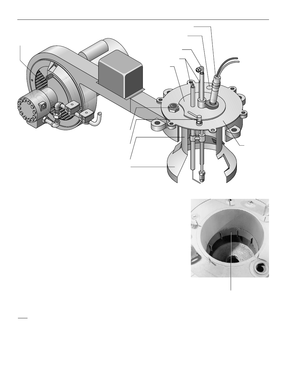
Checking the Stainless Steel
Combustion Ring on Fulton
Oil Fired Steam Boilers
a) The stainless steel combustion
ring in Fulton oil fired boilers are
designed to bring quick and effec-
tive flame transfer to the fire
wall. The ring should fit securely
and tight against the furnace wall for
best results.
b) The ring should be inspected for
distortion in the event of poor com-
bustion which could result in flame
failures.
29-O 4/00
Stainless
Steel
Combustion
Ring
Primary
Air Gate
Secondary
Air Gate
Observation
Port
Blast Tube
Cad Cell (4–15 HP)
Electrodes
Oil Inlet
Scanner Location
(20–60 HP)
Burner
Plate
Air Deflector
Top Plate