Description/instructions – Fulton Classic ICX or FB-F Vertical Tubeless Boilers (Steam) Oil Fired User Manual
Page 19
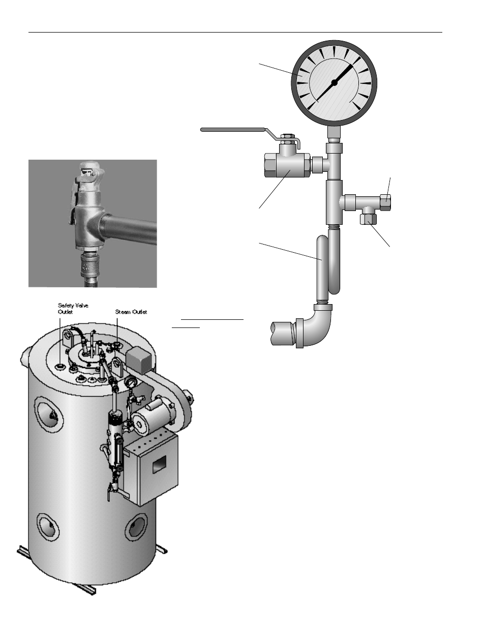
Description/Instructions
Boiler Installation
The Steam Supply — Pipe the
steam supply line from the top right
side of the boiler.
The Steam Safety Valve
1) Before installing, be sure that all
pipes and connections have been
blown clean. Pipe compound or
dope is used on external threads
only. Be sure inlet of valve is free of
any foreign material.
2) Do not use a pipe
wrench! When making
installation, use proper
type and size wrench
3) The valve should be
installed in a vertical upright
position in the connection pro-
vided on the top left side of
the boiler with no unneces-
sary intervening pipe.
Under no circumstances
should there be a shut off
valve or restriction of any
kind between the safety
valve and the connection
provided.
4) Do not cap or plug drain
hole in the side of valve
body.
5) Since the purpose of this
safety valve is to protect
against an overpressure situation, it
will loudly discharge hot steam in
doing so. Therefore, it is recom-
mended that a discharge pipe be
securely installed and run to a safe
point of disposal.
6) When a discharge pipe is used,
it must be of a pipe size equal to or
greater than that of the valve outlet.
Use schedule 40 discharge pipe
only. Do not use schedule 80, extra
strong or double extra
strong discharge pipe or
connections. It must be as
short and straight as possible
and so arranged as to avoid undue
stress on the valve. It must have
an ample provision for draining con-
densate at or near the valve outlet.
It must terminate freely to atmos-
phere with no intervening valve of
any description and it must be
securely anchored and supported.
The Steam Pressure Gauge
Assembly — The gauge should be
facing front towards the panel box
and/or operator of the boiler.
Except as noted, each assembly or
any of its component parts may be
oriented, other than as shown to
provide improved operating clear-
ances and/or view of gauge.
Before installing steam gauge on
the siphon, add a small amount of
water to the siphon to create a
water seal to buffer the gauge ele-
ment. This must be done to prevent
inaccurate pressure readings and
/or premature failure of the gauge.
Install the steam gauge into the
siphon on the water column.
11-O 4/00
Steam
Pressure
Gauge
Steam Gauge
Test Valve
Steam
Siphon Loop
To High Limit
Pressure
Control
To Operating
Pressure
Control