Operation, Operating temperature controls – Fulton Alliance (FT-HC) Horizontal Coil Thermal Fluid (hot oil) Heater User Manual
Page 59
Questions? Call (315) 298-5121, or visit us online at www.fulton.com
SECTION 3
FTHC-IOM-2012-1001
OPERATION
3-23
!
WARNING
Do not operate, or allow others
to operate, service or repair this
equipment unless you (they) fully
understand all applicable sections
of this manual and are qualifi ed to
operate/maintain the equipment.
Non-Fulton product information is for
reference purposes only. No Fulton
document may substitute for full
review of documentation available
from the component manufacturer.
Operating Temperature Controls
The operating temperature control (Siemens, Fireye, Honeywell) are located
in the heater panel and regulate the cycling of the heater. On systems with
linkageless modulation, the operating temperature control and operating control
(fl ame programmer) are the same device.
1. The Coil Design unit is a fi red heat exchanger and the safe control and
monitoring of the thermal fl uid temperature is of vital importance. The safe
maximum temperature of the fl uid must be strictly adhered to.
2. When consulting fl uid manufacturer’s literature for the safe maximum fl uid
temperature, note that the temperatures quoted are the actual limit to
which any of the fl uids may be subjected. It is important to remember that
in any fi red heater there exists a “fi lm” temperature which is higher than the
temperature of the bulk of the fl uid. Temperature controllers measure the
bulk temperature and not the fi lm temperature. This must be taken into
consideration when setting the temperature controls.
3. Approximate guidelines for temperature settings are not to override the
system design parameters.
4. These instructions should be used in conjunction with information from
the system designer. Consult manufacturer’s literature.
5. Standard primary temperature control sensing point location for On/Off
and Modulating heaters is on the heater outlet. For systems with multiple
heaters manifolded together, the sensing point is on the heater inlet.
6. When optional inlet location of the primary controls is specifi ed, the
following instructions may still be used with some modifi cation. For
instance when primary controls are located on the inlet, the dead band
range will be much narrower than on heaters with outlet control. In
addition, temperature changes will not be as immediately apparent.
7. An indicating temperature controller is used to regulate the thermal fl uid
temperature. Typically the indicating control is a thermocouple.
8. The thermocouple is directly immersed in the thermal fl uid in the heater
manifold. The setpoint of the controller is regulated by the keypad.
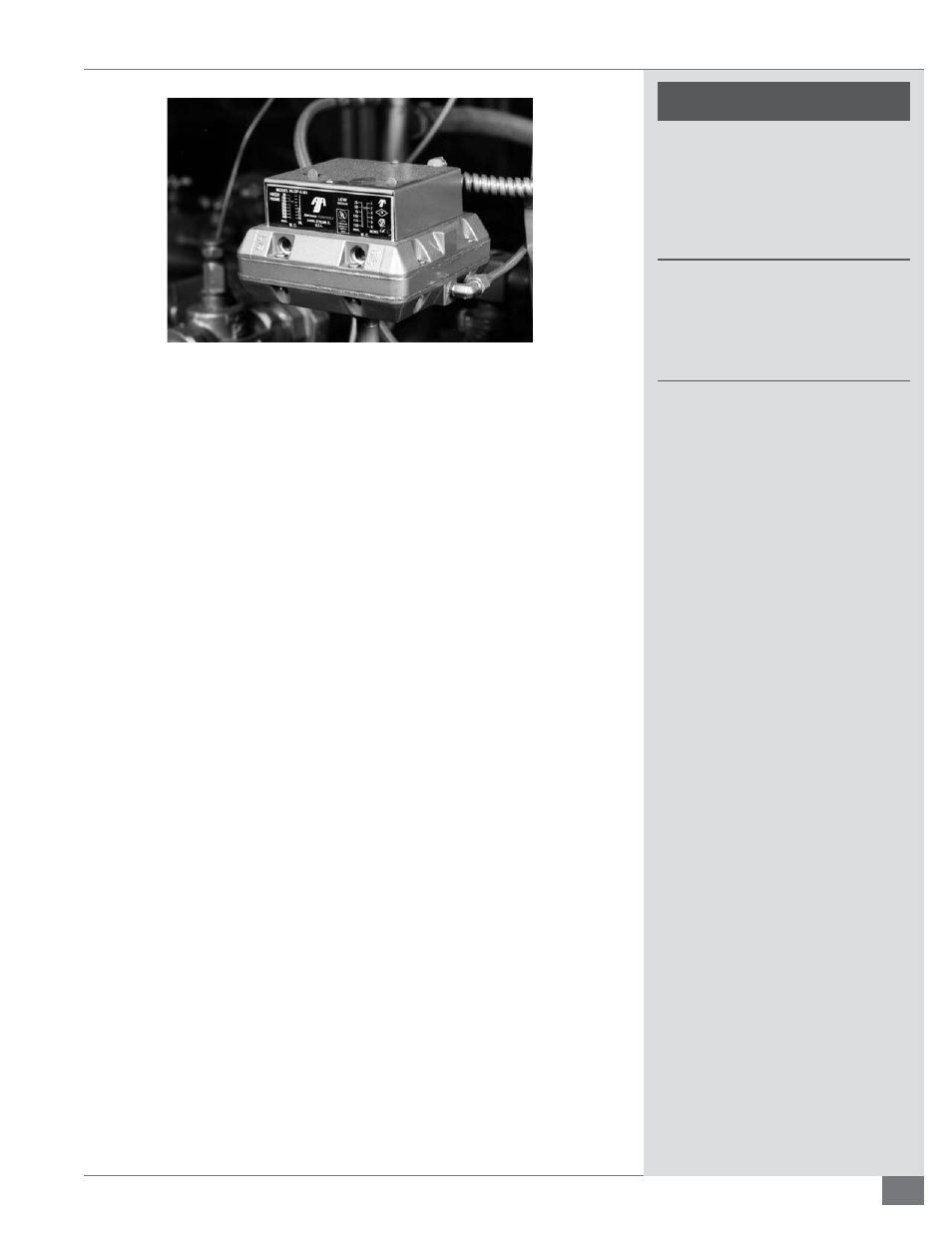
FIGURE 19 - HIGH/LOW GAS PRESSURE SWITCH