Installation – Fulton Alliance (FT-HC) Horizontal Coil Thermal Fluid (hot oil) Heater User Manual
Page 23
Questions? Call (315) 298-5121, or visit us online at www.fulton.com
SECTION 2
FTHC-IOM-2012-1001
INSTALLATION
2-17
7
6
3
8
9
13
11
10
12
14
15
16
17
19
18
2
1
4
5
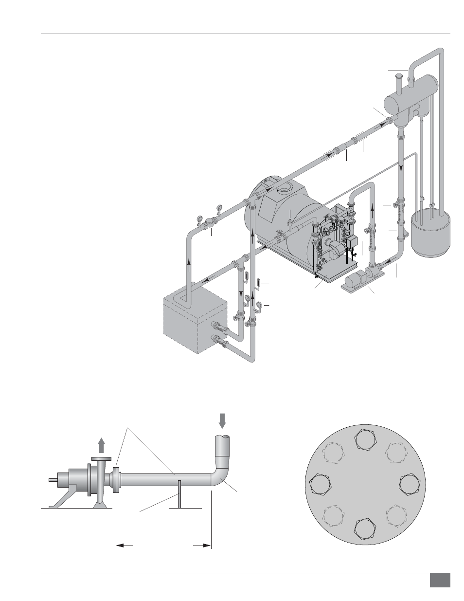
1. Thermal Fluid Heater
2. Thermal Fluid Circulating Pump
3. Safety
Relief
Valve
4. Thermometer
5. Pressure
Gauge
6. Thermal Fluid Heated Equipment
7. Bypass Valve to maintain full fl ow to heater
8. Expansion Joints as required
9. Anchor and Pipe Guides
10. Expansion
Tank
11. Vent Piping (should be full size of expansion tank vent)
12. Deaerator
Tank
13. Deaerator Tank Inlet (must be highest point of piping)
14. Thermal
Buff er Tank
15. Catch Tank for drain of pressure relief valve, cold seal,
expansion tank, and vent. Locate in safe area.
16. Gate
valve
17. Strainer
18. 3/4” System Fill Connection
19. Flexible Connection as necessary
20. Isolating Valve as necessary
21. Manual Low Level Test Line
22. Manual High Level Test Line
23. Buff er Drain
FIGURE 6 - TYPICAL THERMAL PIPING SCHEMATIC
Pump
Pipe Must Be
Diameter of
Pump Intake
From Outlet of Deaerator
First
Fitting
Pipe Support Must Be
Provided (Not To Be
Welded On Both Ends)
6 - 10 Pipe Diameters
FIGURE 7 - TYPICAL PUMP PIPING
1
2
3
4
5
6
7
8
FIGURE 8 - BOLTING SEQUENCE FOR 4 AND 8 BOLT FLANGES