Installation, Vent connections, Catch tank – Fulton Alliance (FT-HC) Horizontal Coil Thermal Fluid (hot oil) Heater User Manual
Page 29
Questions? Call (315) 298-5121, or visit us online at www.fulton.com
SECTION 2
FTHC-IOM-2012-1001
INSTALLATION
2-23
Vent Connections
Adhere to the following for vent connections:
1. Make vent connection in a manner that will prevent
penetration of water or foreign bodies into the tank.
This connection must always terminate in a safe, well
ventilated area and has to be free of obstruction, open
to atmosphere, and arranged in such a manner that,
in the event of discharge from the system, thermal
fl uid could drain into a catch tank without danger to
personnel or property.
2. Make the vent run the same size as the tank outlet. It
should run pitch down from the outlet of the tank to
the catch tank.
3. If nitrogen is used on the system, the vent can be
reduced to 2” (51 mm) and should be piped with a
positive closing valve at the catch tank.
4. Ensure the connection between the tank outlet and the
horizontal pump inlet is as close to a vertical drop as
possible. It should have the minimum bends and length
of pipe.
5. Ensure the inlet to the deaerator is higher than or equal
to the highest point in the system, or a pressurized
system must be used.
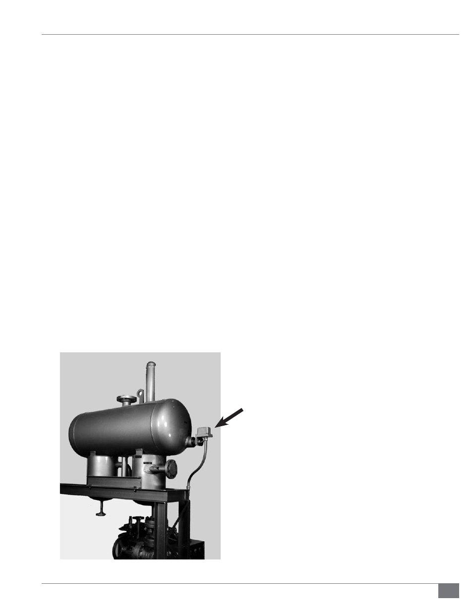
FIGURE 13 - LIQUID LEVEL SWITCH LOCATION
6. Field-install the liquid level switch (supplied and
shipped with the unit). This must be wired to the
control panel.
7. Ensure test connections are accurate. The high and low
level test connections are 1/2” NPT, and are located on
the end of the tank opposite the inlet. The low level
is on the center line of the expansion tank, the high
level is next to it, slightly off center. The high level rises
up from the bottom of the tank and ends 4” (102 mm)
below the top; the low level rises 2” (51 mm) from the
bottom of the tank.
8. Both the high and low level connections should be
piped to a safe catchment. Valves should be installed in
these lines at the catch tank. Installation of the valves
should be accomplished in such a manner that any fl ow
will be visible when the valves are open.
9. Flow from the high level test connection indicates
a tank that is too full; no fl ow from the low level test
connection indicates too little fl uid.
10. There is a 300 #, raised face, fl anged drain on the
bottom of the thermal buff er section, for the purpose of
draining the tank when necessary. This should be piped
with a valve in the line, to a safe catchment. The valve
specifi cations outlined above apply to this valve as well.
11. An inspection opening is located at the highest point
on the tank. Access to this port is recommended but
not required.
12. Refer to the maintenance schedule for
recommendations on draining the buff er tank. For
positioning of all connections on tank, see Figure 12.
Catch Tank
Adhere to the following for the catch tank:
1. Ensure the heater safety relief valve outlet and
connections on the DA tank are piped to a safe catch
tank. The catch tank must be appropriately sized based
on the system volume and confi guration.
2. Under normal operating conditions, the catch tank
should be empty. Fluid that is expelled into the tank
should not be reintroduced into the system.
3. Ensure the vent from the catch tank is located and
installed in such a manner as to protect personnel and
property from discharge of steam, water, and thermal
fl uid. Vent outlet should be positioned in a safe location
outside the heater room.