Installation, Sizing the expansion tank for the system – Fulton Alliance (FT-HC) Horizontal Coil Thermal Fluid (hot oil) Heater User Manual
Page 26
© The Fulton Companies 2012
INSTALLATION
FTHC-IOM-2012-1001
SECTION 2
2-20
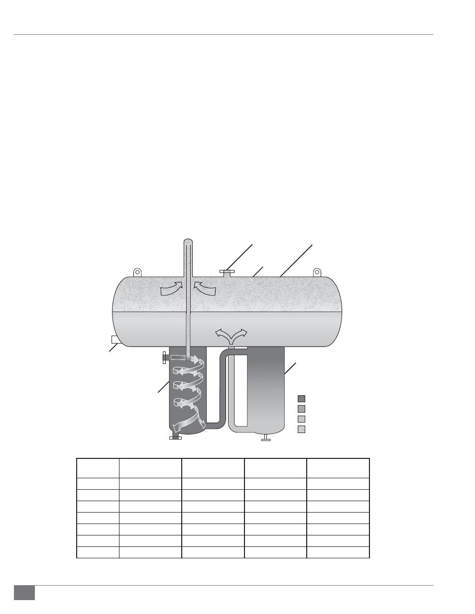
Sizing The Expansion Tank For The System
Expansion tank capacity is the total volume of the tank (see
Figures 11 and 12). It is necessary to have some air space
available at the top of the tank to avoid spillage or overfl ow.
At initial fi ll (for system volume calculations) the deaerator
and cold seal sections must be fi lled completely and the
expansion section must be fi lled to a level of 4 inches (102
mm) to “make” the liquid level switch.
The volume between the initial fi ll level and the safe “full” level
is the amount available for expansion. That volume is used to
decide which tank is suitable for the system expansion.
air to be vented from the system on a continuous basis
during operation to avoid oxidation of the thermal fl uid, and
removes other volatile particles generated by the fl uid itself
during system operation. This section of the tank must be
insulated.
A system of interconnecting pipe work in the thermal buff er
tank section prevents the movement of any oil that has not
cooled suffi
ciently into the expansion section. This avoids
contact of very high thermal fl uid temperature with oxygen
contained in the atmosphere, which causes fl uid breakdown.
DO NOT insulate this section.
Vent for Piping
to Safe Catchment
Expansion
Tank
Liquid
Level
Switch
Fluid Out
Fluid In
Deaerator
Section
Thermal
Buffer
Section
Hot Fluid
Medium Fluid
Cool Fluid
Gases (Steam)
Expansion
Volume
Drain
Model
Capacity (gallons)
Initial Fill (gallons)
Available for
Expansion (gallons)
Max System
Volume
FT-200-L
52
25
46
184
FT-500-L
132
40
121
525
FT-1000-L
264
80
232
1000
FT-1500-L
397
90
380
1400
FT-2000-L
528
145
444
1700
FT-3000-L
793
215
717
2600
FT-5000-L
1310
300
1168
4600
FIGURE 11 - EXPANSION TANK DETAILS