Installation, Requirements for water cooled pumps, Warning – Fulton Alliance (FT-HC) Horizontal Coil Thermal Fluid (hot oil) Heater User Manual
Page 25
Questions? Call (315) 298-5121, or visit us online at www.fulton.com
SECTION 2
FTHC-IOM-2012-1001
INSTALLATION
2-19
!
WARNING
All information in this manual is for
reference and guidance purposes,
and does not substitute for required
professional training, conduct,
and strict adherence to applicable
jurisdictional/professional codes and
regulations.
Non-Fulton product information is for
reference purposes only. No Fulton
document may substitute for full
review of documentation available
from the component manufacturer.
Requirements for Water Cooled Pumps
Adhere to the following for water cooled pumps (See Figure 10):
1. Requirements for water cooled pumps will vary with manufacturer.
Consult manufacturer’s instructions for fl ow rate and temperature
requirements.
2. Check local codes regarding disposal of hot water.
Combination Deaerator/Thermal Buff er/Expansion Tank
Fulton Thermal’s effi
cient design combines the operation of the expansion,
deaerator, and thermal buff er tanks. Installation is considerably simplifi ed by
virtue of this arrangement.
The expansion section is vital to the thermal fl uid system. From ambient to
operating temperature, the thermal fl uid in the system will typically expand
in the range of 25% to 50%, and a vessel capable of handling this expansion is
mandatory. The customer should confi rm the expansion rate of the chosen fl uid
and system volume.
At start up, the primary purpose of the deaerator section is to remove all volatiles
from the system to avoid pump cavitation. The deaerator section also allows
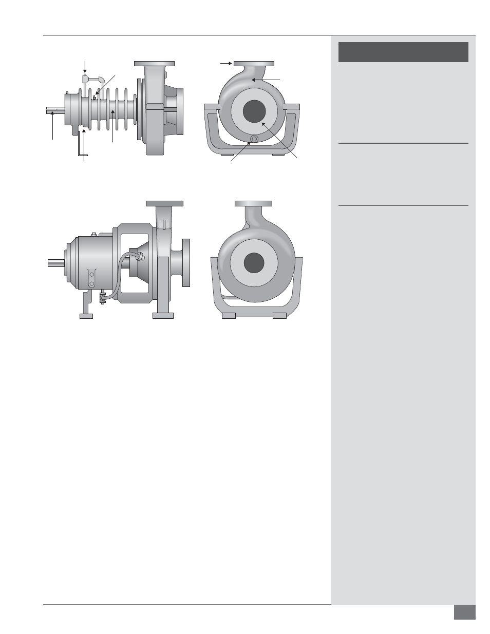
3/8” NPT BARRIER OIL
FILL-MECH. SEAL ONLY
3/8” NPT BEARING GREASE
RELIEF AND LIP SEAL
FAILURE DETECTION
1/8” NPT VENT
1/8” NPT
GREASE FITTING
1/2” NPT CASING DRAIN
WHEN SPECIFIED
1/2” NPT DISCHARGE
GAUGE CONNECTION
WHEN SPECIFIED
DISCHARGE
SUCTION
1/4” X 1/8”
KEYWAY
PUMPAGE
LEAK DETECTION
MECH. SEAL ONLY
FIGURE 9 - TYPICAL AIR COOLED PUMP
FIGURE 10 - TYPICAL WATER COOLED PUMP