Installation, Utilities, The gas supply – Fulton Alliance (FT-HC) Horizontal Coil Thermal Fluid (hot oil) Heater User Manual
Page 12
© The Fulton Companies 2012
INSTALLATION
FTHC-IOM-2012-1001
SECTION 2
2-6
!
WARNING
A qualifi ed installer, service agency
or the gas supplier must perform
installation and service on the fuel
delivery system.
Do not use matches, candles, fl ame or
other sources of ignition to check for
gas leaks.
What to do if you smell gas:
Do not try to light the appliance.
Do not touch any electrical switch.
Do not use any phone in the building.
Leave building and contact gas
supplier from neighbor’s phone. If you
cannot reach gas supplier, phone the
fi re department.
When making gas piping joints,
maintain proper ventilation to reduce
breathing hazards.
An exhaust fan may draw products
of combustion into the work
environment creating a possible
hazard to personnel.
Assure all electrical connections are
powered down prior to attempting
replacement or service of electrical
components or connections of the
equipment.
4
CAUTION
It is essential that only fresh air be
allowed to enter the combustion air
system. Foreign substances, such
as combustible volatiles and lint in
the combustion system can create
hazardous conditions. If foreign
substances can enter the air stream,
the combustion air inlet must be piped
to an outside location. Failure to do so
will void the warranty.
To avoid failures due to poor
combustion, ensure make-up air
system is properly designed.
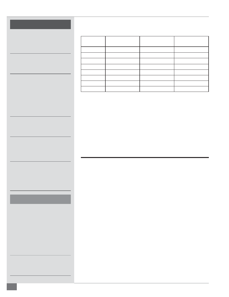
TABLE 4- MINIMUM MAKE-UP AIR REQUIREMENTS AND RECOMMENDED AREA OF
OPENING FOR VENTS
Model
Minimum Make-Up
Air (SCFM)*
Opening Area (in
2
)**
Lower Vent
Opening Area (in
2
)
Upper Vent
FT-0240-HC
600
1200
400
FT-0400-HC
1000
2000
670
FT-0600-HC
1500
3000
1000
FT-0800-HC
2000
4000
1335
FT-1000-HC
2500
5000
1670
FT-1200-HC
3000
6000
2000
FT-1600-HC
4000
8000
2664
FT-2000-HC
5000
10,000
3330
* Minimum make-up air requirements are based on 25% excess air at high fi re.
** Opening areas are calculated based input of a single heater and do not account for the ventilation
needs of the equipment room. These measurements are subject to state and local regulations.
NOTE:
A properly designed make-up air system in the equipment room will
preclude these possibilities and is required to maintain proper combustion.
7. Eliminate potential for high risk situations for particulate matter to
be in the combustion air supply (e.g., as a result of construction and
maintenance activities).
Utilities
The Gas Supply
Adhere to the following for gas supply installation:
1. Install gas piping in accordance with all applicable codes.
2. Ensure pipe and fi ttings used are new and free of dirt or other deposits.
3. Ensure piping is of the proper size for adequate gas supply to the gas head
assembly. Consult your gas company for specifi c recommendations.
4. When making gas piping joints, use a sealing compound resistant to the
action of liquefi ed petroleum gases. Do not use Tefl on tape on gas line
heads.
5. Ensure no piping stresses are transmitted to the equipment. The
equipment shall not be used as a pipe anchor.
6. Ensure all vent connections on diaphragms, gas valves, pressure regulators,
and pressure switches (gas-fi red units) are vented per local code.
7. On
gas-fi red units with NFPA valve trains, ensure the vent valve is piped to
atmosphere per local code.