Installation, The oil supply – Fulton Alliance (FT-HC) Horizontal Coil Thermal Fluid (hot oil) Heater User Manual
Page 13
Questions? Call (315) 298-5121, or visit us online at www.fulton.com
SECTION 2
FTHC-IOM-2012-1001
INSTALLATION
2-7
8. During any pressure testing of the system at pressures
in excess of 1/2 psig (14 inch W.C.)., disconnect the
heater at the heater manual shutoff valve (located at
the end of the supplied gas train) from the gas supply
piping system.
9. Ensure the supply pressure is regulated by a non-
stacking, tight, shut-off regulator.
10. Arrange gas piping so that it does not interfere with
any cover or burner, inhibit service or maintenance,
or prevent access between unit and walls or another
unit.The burner assembly and gas controls terminate
at a manual stop valve to which the gas supply should
be connected. Piping must be sized for a gas fl ow
consistent with the required BTU/Hr input. Large
pressure drops must be avoided. Fulton recommends
that the supply piping between the pressure regulator
and the inlet to the heater be kept to a minimum. The
minimum required gas pressure at the stop valve varies
with the model of heater.
NOTE:
Even when the unit is shut down, the gas supply
pressure must never exceed these values.
NOTE:
When operating, the supply pressure must not drop
below these limits: Not less than 11 “ w.c. where 14” w.c is
required. Not less than 50” w.c. where 60” w.c. is required.
Not less than 100” w.c. where 120” w.c. is required.
11. Some fuel train confi gurations are require a safety relief
valve which must be piped to a safe area in accordance
with local codes.
12. After gas piping is completed and before wiring
installation is started, carefully check all piping
connections, (factory and fi eld), for gas leaks. Use a soap
and water solution.
The Oil Supply
Fuel Oil
Viscosity
Specifi c Gravity
Sulfur Content
#2
Less than
31.9 Seconds
Redwood #1 at
100°F (38°C)
0.824 to 0.852 at
59 C (15°C)
less than 0.40%
by weight
#4
Less than
81 Seconds
Redwood #1 at
100°F (38°C)
0.90 to 0.93 at 59
C (15°C)
less than 0.1.6%
by weight
#6
Less than 3000
Seconds Red-
wood #1 at 100°F
(38°C)
0.95 to 0.98 at
59°F (15°C)
less than 2.12%
by weight
Adhere to the following for installation:
1. Fuel pipes must be of approved materials and of a
diameter suitable for the quantity of oil being delivered to
the burner and the static head available. See .
2. Make fuel connection in accordance with the details on
the enclosed fuel pump cut sheet.
3. Ensure fuel oil piping is in accordance with local and/or
national requirements. In addition, if a two pipe system
is employed, a check valve must be fi tted into the return
pipe.
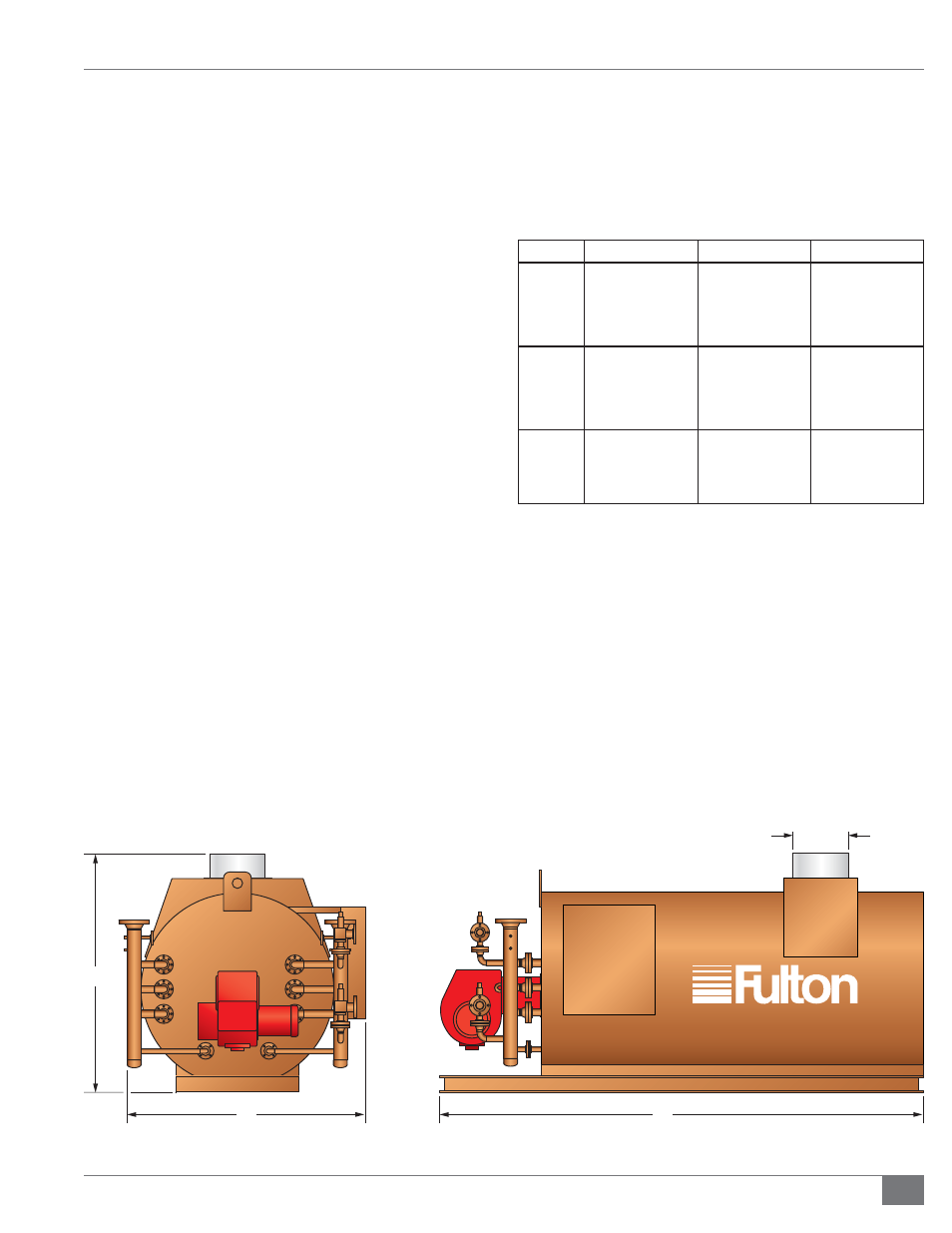
FIGURE 2 - DIMENSIONS (REFER TO TABLE 2)
A
C
D
B