Installation – Fulton Alliance (FT-HC) Horizontal Coil Thermal Fluid (hot oil) Heater User Manual
Page 11
Questions? Call (315) 298-5121, or visit us online at www.fulton.com
SECTION 2
FTHC-IOM-2012-1001
INSTALLATION
2-5
5. If positive forced ventilation is adopted, ensure that
there will be no appreciable pressure variation in the
equipment room.
6. Avoid ventilation which creates a negative pressure
in the building as it will seriously aff ect combustion
and proper operation of the stack. Please note that
exhaust fans or similar equipment can create a down
draft in the chimney or starve the burner’s air supply.
Either case may result in poor combustion or nuisance
failures. A properly designed make-up air system in the
equipment room will preclude these possibilities and is
required to maintain proper combustion.
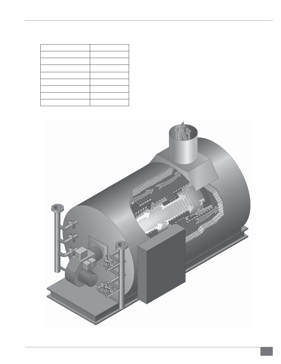
FIGURE 1 -COMPONENT VIEW OF THE FTHC HERMAL FLUID HEATER
Notes:
1. The burner fi res down the center of the coil.
2. The hot gases return between the coils to the front end plate,
then fl ow to the back of the heater and exit out the fl ue.
TABLE 3- APPROXIMATE FLOOR LOADING
(BASED ON OPERATING WEIGHT)
Model
Heater Only*
FT-0240-HC
125
FT-0400-HC
200
FT-0600-HC
260
FT-0800-HC
200
FT-1000-HC
300
FT-1200-HC
300
FT-1600-HC
325
FT-2000-HC
300
*All weights are lbs/ft2