Maintenance – Fulton Vertical Tubeless (FT-A) Thermal Fluid (hot oil) Heater User Manual
Page 73
Questions? Call (315) 298-5121, or visit us online at www.fulton.com
SECTION 4
FTA-IOM-2013-0227
MAINTENANCE
4-13
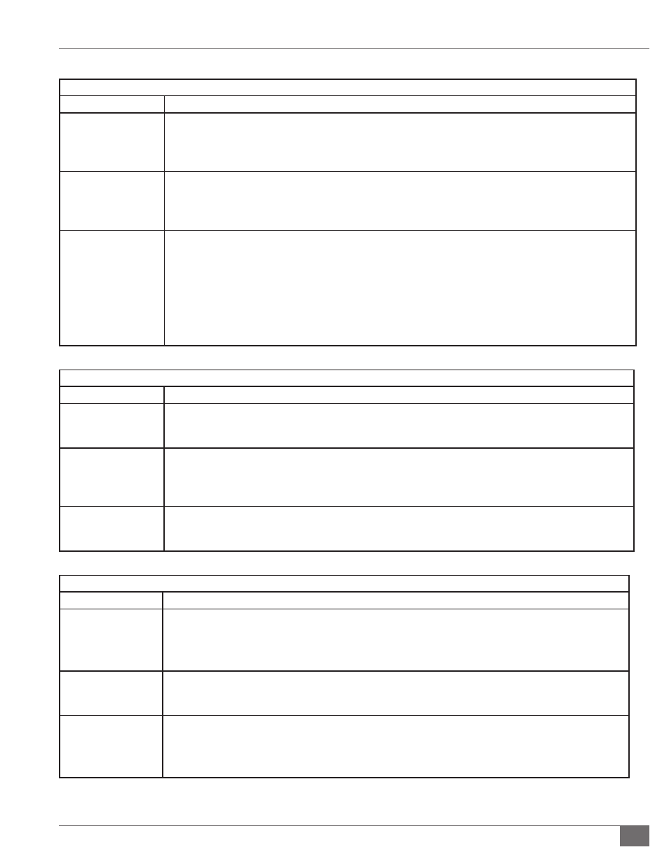
TABLE 10-E - CALL FOR HEAT CIRCUIT TROUBLESHOOTING
Problem
Potential Remedy
Temperature Controller
Failure
If the temperature controller is calling for heat but is not putting power on the output to the control relay, the relay
will not close the normally open contacts and the heater will remain disabled. If this is the case, some controllers
have separate sets of contacts that may be utilized in replacement of the damaged contacts. Some rewiring and/or
reprogramming will be needed. Contact Fulton service department if necessary.
Temperature Sensor
Failure
Diff erent temperature controllers use diff erent types of temperature sensors. These may be Type J thermocouples,
mercury bulbs, RTDs or another type of sensor. It is possible for these sensors to malfunction. To verify proper
sensor operation, use an alternate source of temperature detection such as an infrared temperature sensor to sense
temperature at the same point.
Control Relay May Have
Failed
Many temperature controllers energize a relay with a call for heat that in turn closes a normally open set of contacts to
energize the burner circuit.
If your temperature controller is sending an output signal to the control relay but the burner is not initiated, check
resistance across the relay. An open reading indicates that the relay needs to be replaced. If the coil shows resistance,
energize coil and check contacts. With coil energized, normally open contacts should close resulting in a reading of
control voltage on both the common and normally open contact.
If voltage exists on common but not on normally open contact either switch contacts if another set of normally open
contacts are available or replace relay.
TABLE 10-F - AIR SWITCH TROUBLESHOOTING
Problem
Potential Remedy
Combustion Blower Fan
is Dirty
If the cups of the squirrel cage type fan become dirty, less air will be moved by the fan. If the fans are dirty enough,
there will not be enough air fl ow for the air switch to prove. You should assure that the combustion blower fan is
clean, reset the fl ame programmer and try to light unit again
The sensing line is
plugged, crimped or
pointing in the wrong
area
If the sensing line to the air switch is crimped or blocked, the switch will not sense the proper pressure. Ensure that
the sensing line is clear and not crimped by removing both sides of the sensing line and using compressed air to
blow through the line. Also ensure that the elbow acting as an air scoop is pointing directly into the air stream. Reset
the fl ame programmer and try to light the unit again.
The Switch setting is
improper
The adjustment screw for the air switch is located opposite the electrical connections. A gray cap covers the screw.
Turn the screw clockwise to increase setting, counter-clockwise to decrease setting. To set switch, run unit at low fi re.
Increase setting 1/2 turn every 5 seconds until unit trips on interlock. Decrease setting by 2 full turns. Reset unit.
TABLE 10-G - AIR FILTER SWITCH TROUBLESHOOTING
Problem
Potential Remedy
The air fi lter is dirty
If the air fi lter becomes dirty, the fan will generate greater suction. Too much suction will result in not enough airfl ow
for proper combustion and mixing and will cause air switch to trip. You should regularly change fi lters on a schedule
dependent on how dirty the makeup air is. After checking or changing air fi lter, reset the fl ame programmer and try to
light unit again.
There is an obstruction
in the make-up air
ducting
Units that have make-up air ducting need to assure that blockage to the ducting does not occur. Check outside
termination and any bends in the ducting for blockage. Clear blockage, reset fl ame programmer and try to light unit
again.
The sensing line is
pointing in the wrong
direction
The sensing line for the air fi lter switch is supposed to provide the static pressure of the air box. The termination of the
sensing line should be pointing in the direction that limits its contact with moving air. If the sensing line is pointed
perpendicularly to entering air stream, the switch will not sense the proper pressure and could give a false indication of
air box suction. Reset the fl ame programmer and try to light the unit again.