Installation, Instrument air, Electrical supply – Fulton Vertical Tubeless (FT-A) Thermal Fluid (hot oil) Heater User Manual
Page 14
© The Fulton Companies 2013
INSTALLATION
FTA-IOM-2013-0227
SECTION 2
2-8
gas at 11“w.c. is required. For details contact a local
liquid propane dealer.
Instrument Air
Instrument air provision for pneumatically actuated
control devices should meet the minimum and
maximum fl ow rate and delivery pressures specifi ed by
the individual equipment. Additionally, it should be a dry,
dust free supply with a dew point of -40 F (-40 C).
Electrical Supply
Adhere to the following for electrical supply installation:
1. Install wiring and ground in equipment in
accordance with authority having jurisdiction
or in absence of such requirements the National
Electrical Code, ANSI/NFPA 70.
2. Provide a wall-mounted, fused disconnect sized for
the unit. This must be fi tted by the client/contractor
if disconnect is not supplied on the panel.
3. Size fuses according to motor name plates and
local electrical codes.
4. Connect power to the terminal strip as supplied on the
inside of the panel box.
NOTE: Single skid systems are generally shipped completely
prewired.
NOTE: The liquid level switch on the expansion tank, when
supplied, will be shipped in the parts box and must be
installed in the fi eld.
5. Determine multiple skid systems wiring requirements
(between the skids). Fulton will run conduit and wire
the devices on each skid. For the devices that have to
come down for shipping, the wire will be left at the end
of the conduit where possible and wired in the fi eld (by
others). When the system has multiple skids that are
adjoining, the conduit will be installed to break at the
skid joints. The wire for the conduit running between
the skids will be shipped loose to prevent damage
when the skids are put back together. These wires
will need to be run by the installing contractor in the
fi eld and wired to proper locations. If there is wiring
between skids that are not adjoining, then this will need
to be done by qualifi ed personnel.
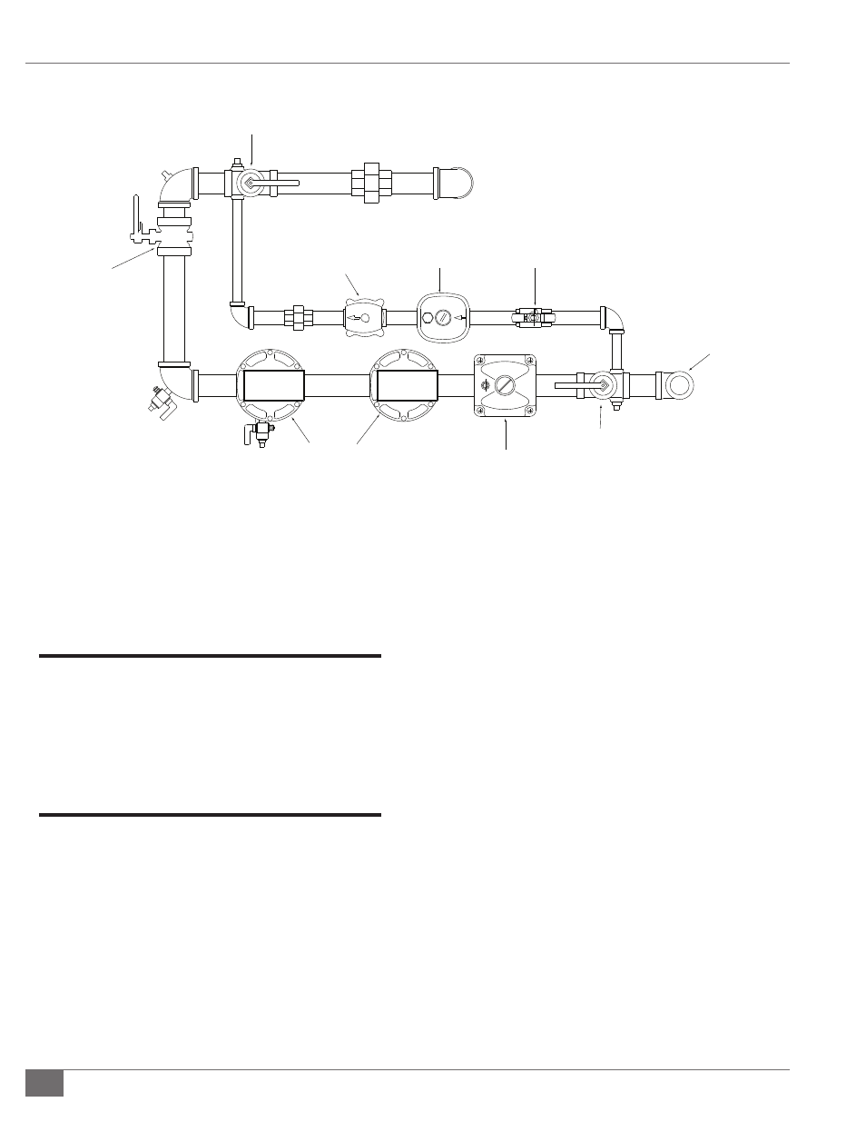
FIGURE 3 - TYPICAL GAS-FIRED MODULATED CSD-1 FUEL TRAIN
1” Gas Connection
Manual
Gas Valve
Manual
Gas Valve
Gas Pressure
Regulator
Diaphragm
Gas Valves
Butterfly
Valve
Pilot Gas
Valve
Pilot Gas
Regulator
Manual
Ball Valve