Installation, Valves – Fulton Vertical Tubeless (FT-A) Thermal Fluid (hot oil) Heater User Manual
Page 34
© The Fulton Companies 2013
INSTALLATION
FTA-IOM-2013-0227
SECTION 2
2-28
!
WARNING
All information in this manual is for
reference and guidance purposes,
and does not substitute for required
professional training, conduct,
and strict adherence to applicable
jurisdictional/professional codes and
regulations.
Once the system has been fi lled,
any modifi cation to the tank or
connected piping requires purging
of the work area to prevent ignition
of potentially fl ammable vapors.
Consult factory prior to beginning
work. Consult Material Safety Data
Sheet (MSDS) for your thermal fl uid
for fl ammability limits.
Valves
Adhere to the following for valve installation:
1. Use vent and drain valves that normally are 1/2” or 3/4” with internal seals
made from materials suited to use with thermal fl uids. They may be of the
screw type if installed on stalks not less than 12” (30.5 cm) long.
2. Use gasketing material specifi cally suited to the task.
3. Fit drain valves at all low points in the pipework system and ventilating
valves at all high points in the installation. Valves must be fi tted with either
the conventional packed stuffi
ng box seal or a bellows seal as required.
4. Where the stuffi
ng box is specifi ed, it should be as deep as possible and
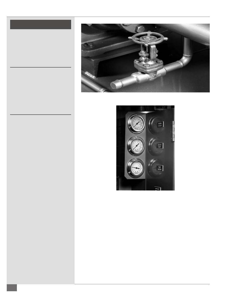
FIGURE 15 - DRAIN AND FILL CONNECTION
FIGURE 16 - GAUGES