Installation – Fulton Vertical Tubeless (FT-A) Thermal Fluid (hot oil) Heater User Manual
Page 22
© The Fulton Companies 2013
INSTALLATION
FTA-IOM-2013-0227
SECTION 2
2-16
nipples welded in the top of the piping with ball valves
and plugs attached are to be used.
NOTE: It will save a considerable amount of time during the
cold fi ltration if the system piping is cleaned prior to assembly.
The mill scale (the results of oxidation) on the inside of the
piping as well as construction debris can foul the fl uid and
cause the need for the fi lters (strainers) to be cleaned more
than need be. This can range from simply using a rag to
ordering pickled pipe. (“Pickling” is a process where the piping
is fi rst soaked in an acid bath, then soaked in a neutralizing
bath, then given a protective oil coating.)
17. Install all pipes with a pitch to facilitate draining and
venting.
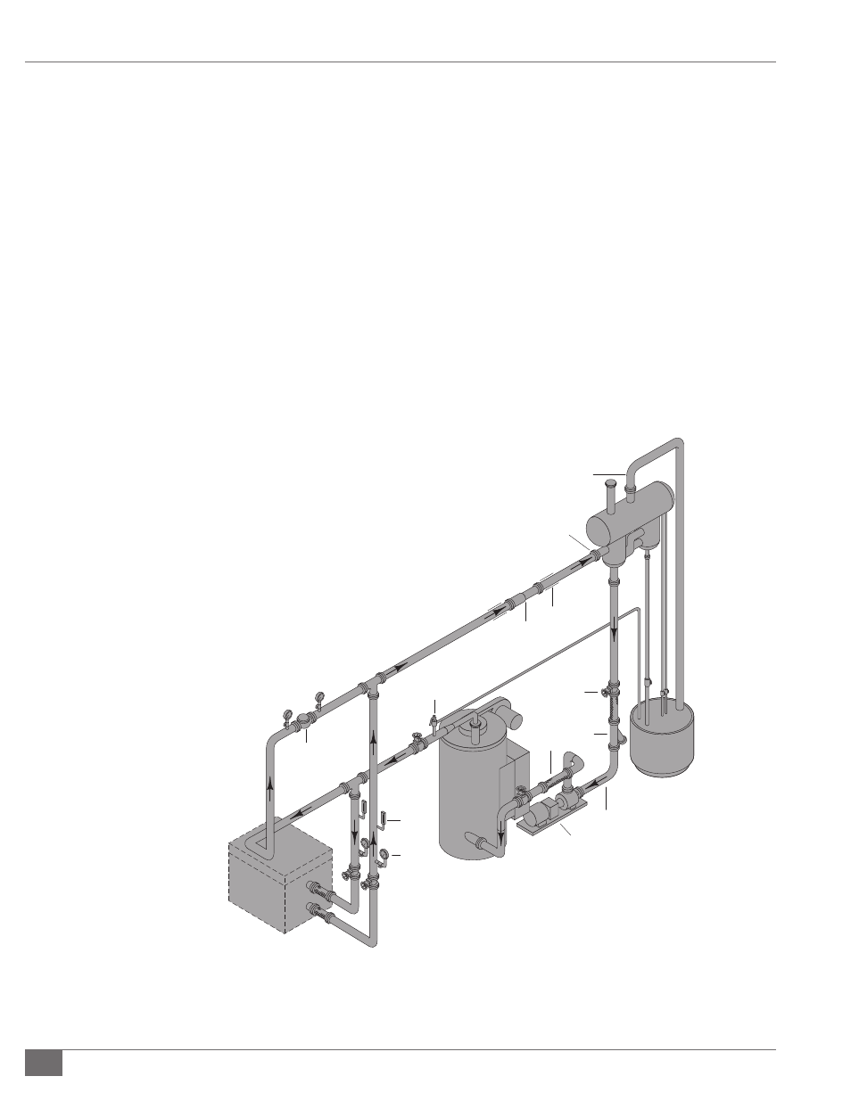
FIGURE 7 - TYPICAL THERMAL PIPING SCHEMATIC
Legend
1. Thermal Fluid Heater
2. Thermal Fluid Circulating Pump
3. Safety Relief Valve
4. Thermometer
5. Pressure Gauge
6. Thermal Fluid Heated
Equipment
7. Bypass Valve
8. Expansion Joints
9. Anchor and Pipe Guides
10. Expansion Tank
11. Vent Piping
12. Deaerator Tank
13. Deaerator Tank Inlet (must be
highest point of piping)
14. Thermal Buff er Tank
15. Catch tank (for drain of
pressure relief valve, cold seal,
expansion tank, vent)
16. Valve
17. Strainer
18. 3/4” System Fill Connection
19. Flexible Connection
7
6
3
8
9
13
11
10
12
14
15
16
17
19
18
2
1
4
5