Installation – Fulton Vertical Tubeless (FT-A) Thermal Fluid (hot oil) Heater User Manual
Page 12
© The Fulton Companies 2013
INSTALLATION
FTA-IOM-2013-0227
SECTION 2
2-6
!
WARNING
All information in this manual is for
reference and guidance purposes,
and does not substitute for required
professional training, conduct, and strict
adherence to applicable jurisdictional/
professional codes and regulations.
A qualifi ed installer, service agency or the
gas supplier must perform installation and
service on the fuel delivery system.
Do not use matches, candles, fl ame or
other sources of ignition to check for gas
leaks.
What to do if you smell gas:
Do not try to light the appliance.
Do not touch any electrical switch.
Do not use any phone in the building.
Leave building and contact gas supplier
from neighbor’s phone. If you cannot
reach gas supplier, phone the fi re
department.
When making gas piping joints, maintain
proper ventilation to reduce breathing
hazards.
An exhaust fan may draw products of
combustion into the work environment
creating a possible hazard to personnel.
4
CAUTION
It is essential that only fresh air be allowed
to enter the combustion air system. Foreign
substances, such as combustible volatiles
and lint in the combustion system can create
hazardous conditions. If foreign substances
can enter the air stream, the combustion air
inlet must be piped to an outside location.
Failure to do so will void the warranty.
To avoid failures due to poor combustion,
ensure make-up air system is properly
designed.
Some soap used for leak testing is corrosive
to certain types of metals. Clean all piping
thoroughly after completing the leak check.
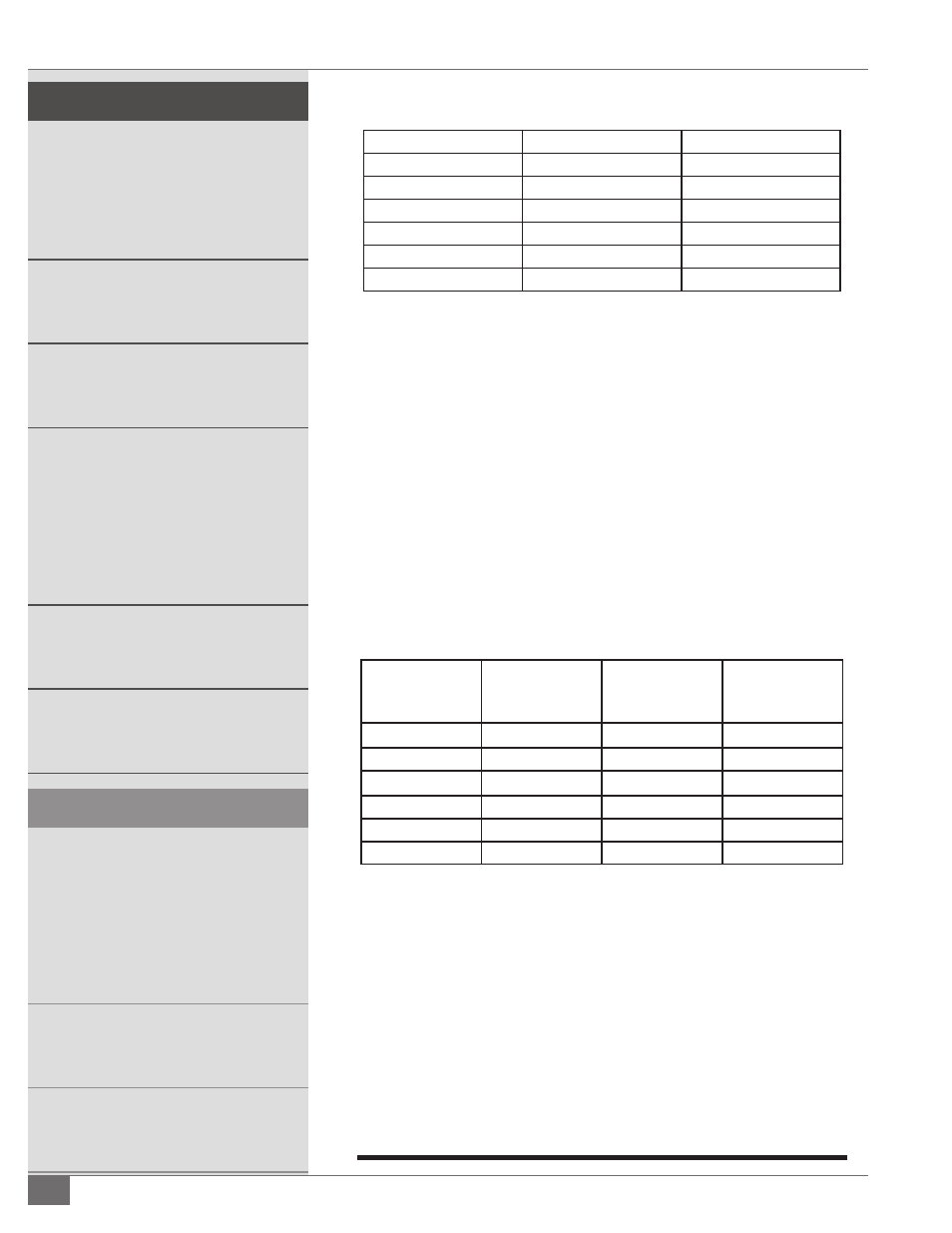
TABLE 3- APPROXIMATE FLOOR LOADING*
Model
Free Standing
Skid Mounted
FT-0200-A
400
250
FT-0380-A
400
250
FT-0520-A
400
200
FT-0690-A
400
250
FT-1050-A
400
300
FT-1740-A
600
400
*All weights are lbs/ft2
3. Ensure the equipment room air supply openings are kept clear at all
times.
4. See Table 4 for minimum make-up air required and the
recommended area of each opening for each model.
5. If positive forced ventilation is adopted, ensure that there will be no
appreciable pressure variation in the equipment room.
6. Avoid ventilation which creates a negative pressure in the building
as it will seriously aff ect combustion and proper operation of the
stack. Please note that exhaust fans or similar equipment can create
a down draft in the chimney or starve the burner’s air supply. Either
case may result in poor combustion or nuisance failures.
TABLE 4 - MINIMUM MAKE-UP AIR REQUIREMENTS AND RECOMMENDED AREA OF
OPENING FOR VENTS
Model
Minimum Make-
Up Air (SCFM)*
Opening Area
(in2) Lower
Vent**
Opening Area
(in2) Upper Vent
FT-0200-A
50
115
40
FT-0380-A
95
195
65
FT-0520-A
130
290
100
FT-0690-A
175
385
130
FT-1050-A
265
585
195
FT-1740-A
435
965
325
*Minimum make-up air requirements are based on 25% excess air at high fi re.
**Opening areas are calculated based input of a single heater and do not account for the
ventilation needs of the equipment room. These measurements are subject to state and local
regulations.
NOTE: A properly designed make-up air system in the equipment room will
preclude these possibilities and is required to maintain proper combustion.
7. Eliminate potential for high risk situations for particulate matter to
be in the combustion air supply (e.g., as a result of construction and
maintenance activities).