Installation, Vent connections – Fulton Vertical Tubeless (FT-A) Thermal Fluid (hot oil) Heater User Manual
Page 32
© The Fulton Companies 2013
INSTALLATION
FTA-IOM-2013-0227
SECTION 2
2-26
!
WARNING
All information in this manual is for
reference and guidance purposes,
and does not substitute for required
professional training, conduct,
and strict adherence to applicable
jurisdictional/professional codes and
regulations.
High temperature thermal fl uid,
steam, and combustible vapors
may be vented through the vent
connection on the combination
deaerator/thermal buff er/expansion
tank.
4
CAUTION
Non-code tanks cannot be pressurized
over 15 psig.
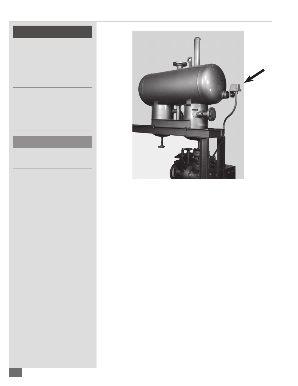
FIGURE 14 - LIQUID LEVEL SWITCH LOCATION
Vent Connections
Adhere to the following for vent connections:
1. Make vent connection in a manner that will prevent penetration of water
or foreign bodies into the tank. This connection must always terminate
in a safe, well ventilated area and has to be free of obstruction, open to
atmosphere, and arranged in such a manner that, in the event of discharge
from the system, thermal fl uid could drain into a catch tank without
danger to personnel or property.
2. Make the vent run the same size as the tank outlet. It should run pitch
down from the outlet of the tank to the catch tank.
3. If nitrogen is used on the system, the vent can be reduced to 2” (51 mm)
and should be piped with a positive closing valve at the catch tank.
4. Ensure the connection between the tank outlet and the horizontal pump
inlet is as close to a vertical drop as possible. It should have the minimum
bends and length of pipe.
5. Ensure the inlet to the deaerator is higher than or equal to the highest
point in the system, or a pressurized system must be used.
6. Field-install the liquid level switch (supplied and shipped with the unit).
This must be wired to the control panel.
7. Ensure test connections are accurate. The high and low level test