Installation – Fulton Vertical Tubeless (FT-A) Thermal Fluid (hot oil) Heater User Manual
Page 30
© The Fulton Companies 2013
INSTALLATION
FTA-IOM-2013-0227
SECTION 2
2-24
!
WARNING
All information in this manual is for
reference and guidance purposes,
and does not substitute for required
professional training, conduct,
and strict adherence to applicable
jurisdictional/professional codes and
regulations.
4
CAUTION
If the deaerator/thermal buff er/
expansion tank is located outdoors, a
nitrogen blanket is required.
1. An automatic venting device must be fi tted to the system expansion tank.
Consult Fulton Thermal Corporation for further details.
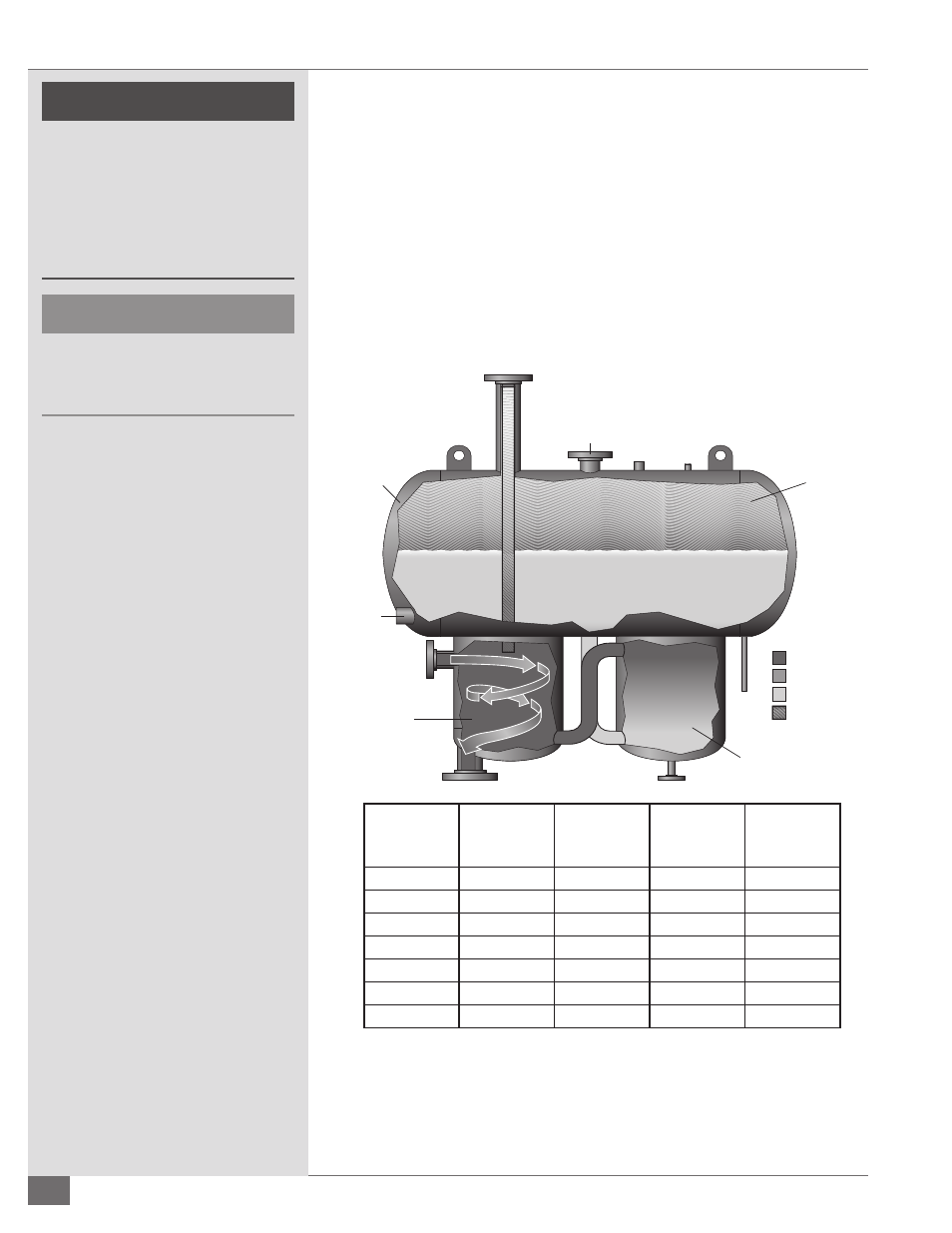
2. The location for the liquid level switch (Figure 14) is a 2-1/2” NPT connection
on the same end of the tank as the inlet. The liquid level switch is supplied
and shipped with the unit, and must be installed by the customer and then
wired to the control panel.
3. If the tank is located outdoors, nitrogen is required.
Model
Capacity
(gallons)
Initial Fill
(gallons)
Available for
Expansion
(gallons)
Max System
Volume
FT-200-L
52
25
46
184
FT-500-L
132
40
121
525
FT-1000-L
264
80
232
1000
FT-1500-L
397
90
380
1400
FT-2000-L
528
145
444
1700
FT-3000-L
793
215
717
2600
FT-5000-L
1310
300
1168
4600
FIGURE 12 - EXPANSION TANK DETAILS
Hot Fluid
Medium Fluid
Cool Fluid
Gases (Steam)
Fluid In
Liquid
Level
Switch
Fluid Out
Drain
Vent for Piping
to Safe Catchment
Expansion
Tank
Deaerator
Section
Thermal
Buffer Section
Expansion
Volume