PASCO ES-9060 Charge, Equipotential and Field Mapper User Manual
Page 9
Charge, Equipotential, and Field Mapper
Model No. ES-9060
8
®
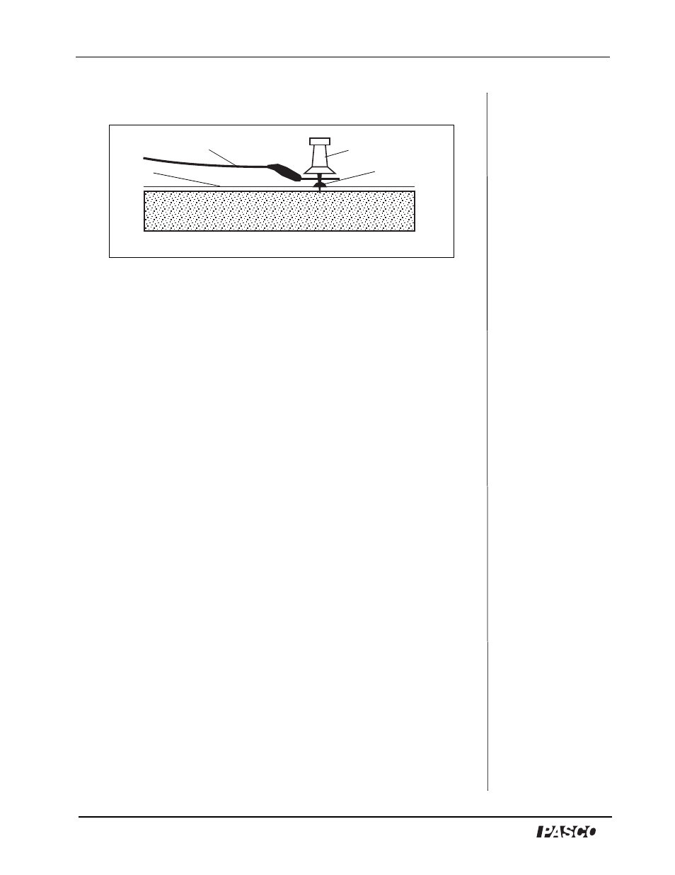
corkboard. Make certain the pin holds the terminal firmly to the
electrode (See Figure 6).
NOTE: Check to see that the terminal which touches the electrode is
clean. A dirty path may result in a bad contact.
3. Connect the other end of the wire to the battery.
4. To check the electrodes for proper conductivity, connect one
voltmeter lead near the push pin on an electrode. Touch the
voltmeter’s second lead to other points on the same electrode. If the
electrode has been properly drawn, the maximum potential between
any two points on the same electrode will not exceed 1% of the
potential applied between the two electrodes.
NOTE: This test can only be made if the potential source is connected
across the two electrodes.
If the voltage across the same electrode is greater than 1% of the
voltage applied between the two electrodes, then remove the paper
from the corkboard and draw over the electrodes a second time with
the conductive ink.
Part III: Plotting an Equipotential
Equipotentials are plotted by connecting one lead of the voltmeter
(ground) to one of the electrode push pins. This electrode now
becomes the reference. The other voltmeter lead (the probe) is used to
measure the potential at any point on the paper simply by touching the
probe to the paper at that point.
1. To map an equipotential, move the probe until the desired potential is
indicated on the voltmeter.
2. Mark the paper at this point with a soft lead or light-colored lead
pencil.
Figure 6: Electrode with connecting wire
connecting wire
push pin
electrode
paper