Introduction – PASCO ES-9060 Charge, Equipotential and Field Mapper User Manual
Page 6
®
Model No. ES-9060
Charge, Equipotential, and Field Mapper
5
Introduction
The PASCO scientific model
ES-9060 Equipotential,
Charge and Field Mapper
consists of two basic
elements. The first is a
carbon impregnated paper in
the resistance range of 5 to 20
K per square. This paper
forms the conducting medium
or space between the
electrodes. The second
element is a conductive ink dispensed from a pen. The ink is produced
from silver particles in a suspension liquid. As the ink dries, the silver
flakes settle on top of each other forming a conductive path (or
conductive ink electrodes). The resistance of the ink is between 0.03
and 0.05 /cm for a 1 mm wide line.
Because the paper has a finite resistance, a current must flow through it
to produce a potential difference. This current is supplied by the
conductive ink electrodes, which causes a potential drop to occur
across the paths. Because of the large difference between the ink’s
resistance and the resistance of the paper, this potential drop is less
than 1% of that produced across the paper. Therefore, for all practical
purposes, the potential drop across the electrodes may be considered
negligible.
To plot equipotentials, charge and field gradients with the ES-9060
Equipotential, Charge and Field Mapper, you will need a voltmeter or
other charge potential measuring device. It would be desirable that the
potential measuring instrument have an infinite impedance. An
electrometer, such as the PASCO Model ES-9054B (or ES-9078)
would be optimal; however, a standard electronic voltmeter, such as
PASCO’s SE-9589 Handheld Digital Multimeter with a 10 M (or
higher) input impedance is sufficient. Since the impedance of a 10
M voltmeter is at least 100 times greater than that of the paper, the
greatest distortion of the field which can be produced by the voltmeter
is approximately 1%.
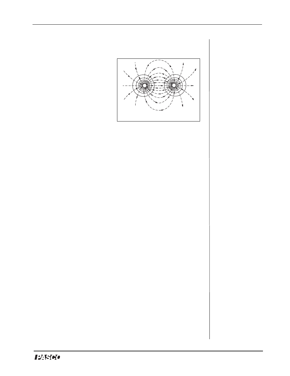
-
+
Figure 1: Equipotential Lines
Ω
Ω
Ω
Ω