Equipment setup – PASCO ES-9060 Charge, Equipotential and Field Mapper User Manual
Page 7
Charge, Equipotential, and Field Mapper
Model No. ES-9060
6
®
Equipment Setup
Part I: Sketching the Charged Paths (Electrodes)
NOTE: The silver conductive ink reaches its maximum conductivity
after 20 minutes of drying time. For optimal results, plan the time
table for conducting the experiments and correlate drawing the
conductive paths accordingly.
1. Plan and sketch the layout (size, shape, and relative spacing) of the
charged path to be studied on a piece of paper. These paths can be any
two dimensional shape, such as straight or curved lines, circles, dots,
squares, etc. Since the charged paths will actually be conductive ink
electrodes, they will be referred to as electrodes.
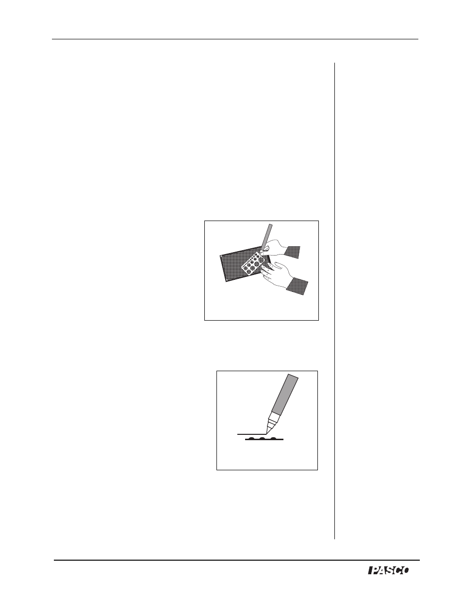
2. Draw the electrodes on the black
paper (See Figure 2).
NOTE: This next steps (a-e) are the
most difficult and crucial part of the
experiment. Follow these steps
carefully.
a) Place the grid conductive paper
printed side up, on a smooth hard
surface. Do not attempt to draw
the electrodes while the paper is on the corkboard.
b) Vigorously shake the conductive ink pen (with the cap on) for 10-20
seconds to disperse any particle matter suspended in the ink.
c) Remove the cap. On a piece of scrap
paper, press lightly down on the
spring-loaded tip while squeezing
the pen barrel firmly. This starts the
ink flowing. Slowly drawing the
pen across the paper produces a
solid line. Drawing speed and
exerted pressure determines the path
width (See Figure 3).
d) Once a satisfactory line is produced
on the scrap paper, draw the electrodes on the grid of the black
conductive paper. If the line becomes thin or spotty, draw over it
again. A solid line is essential for good measurements.
Figure 2: Drawing
electrodes on black paper
Figure 3: Drawing on the
conductive paper