PASCO ES-9060 Charge, Equipotential and Field Mapper User Manual
Page 11
Charge, Equipotential, and Field Mapper
Model No. ES-9060
10
®
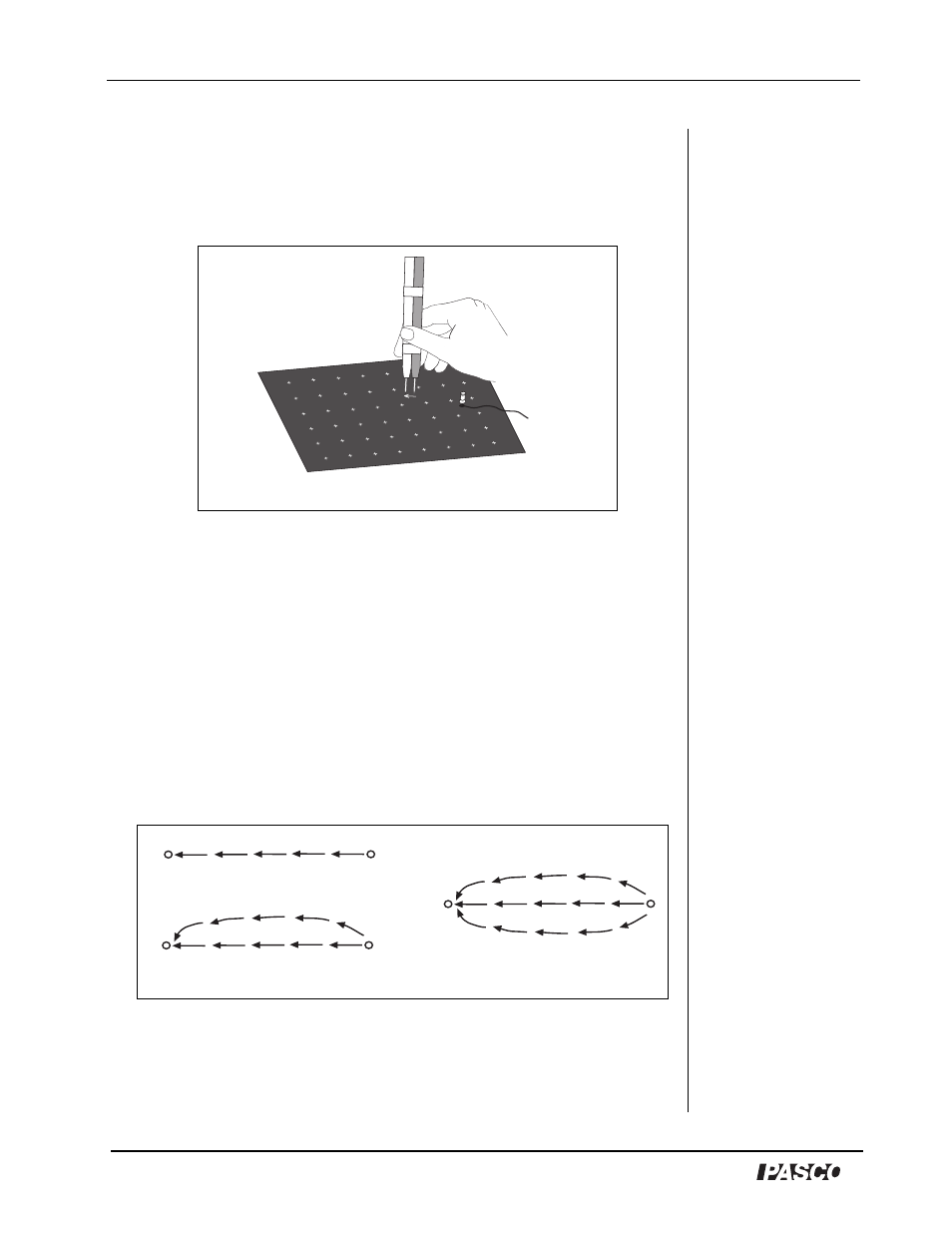
4. When the potential is the highest, draw an arrow on the paper from
the ground lead to the other lead (See Figure 8). Then move the
ground lead to the tip (head) of the arrow. Repeat the action of
pivoting and touching the front lead until the potential reading in a
given direction is highest.
5. Draw a new arrow. Repeat the action of putting the ground lead at
the tip (head) of each new arrow and finding the direction in which
the potential difference is highest. Eventually, the arrows drawn in
this manner will form a field line.
6. Return the dipole and select a new point at which to place the
voltmeter’s ground lead. Again, probe with the other lead until you
find the direction of highest potential difference.
7. Draw an arrow from the ground lead to the other lead, and repeat
the process until a new field line is drawn. Continue selecting new
points and drawing field lines around the original dipole (See
Figure 9).
Figure 8: Moving the leads over the arrow
Figure 9: Example of 3 field lines between unlike dipoles
3rd line
2nd line
1st line
Dipole
Dipole