Using sensors with the arm model, Angle sensor, Force sensor – PASCO ME-6807A Human Arm Model User Manual
Page 7
®
M E - 6 8 0 7 A
U s i n g S e n s o r s w i th th e A r m M o d e l
7
Using Sensors with the Arm Model
Note: For more information about angle sensors, force sensors, and interfaces, see the instruc-
tions supplied with those devices.
Angle Sensor
1.
Connect the cable from the elbow to Channel 1 of the angle sensor.
2.
Connect the cable from the shoulder to Channel 2 of the angle sensor.
3.
Connect the angle sensor to your PASPORT interface.
4.
If you are using a computer, connect the PASPORT interface to it and start
DataStudio.
Force Sensor
1.
Connect a force sensor to the same PASPORT interface as the angle sensor (if it
is a multi-port interface) or to a separate interface.
2.
Use one of the included cord locks to make a loop in the biceps or triceps cord
and attach it to force sensor’s hook (see “Attaching Cords to the Arm Model” on
page 6).
3.
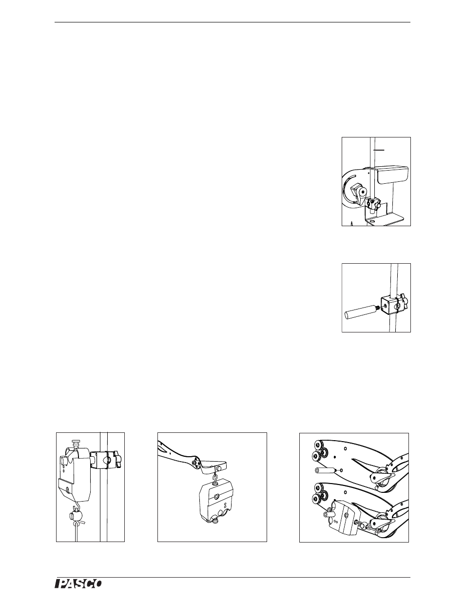
Clamp the included 45 cm rod to the base of the arm model (Figure 9).
4.
Secure the included sensor clamp to the rod. Screw the sensor stud into the clamp
(Figure 10).
5.
Mount the force sensor on the stud (Figure 11).
Repeat steps 1 and 2 to add a second force sensor.
For some experiments, the second force sensor is used to apply a load to the model’s
hand. You can hook the force sensor directly onto the hand, or, for more flexibility, tie
a loop of string to the hand (Figure 12).
To mount a force sensor on the upper arm, screw a sensor stud into one of the
threaded holes. (See Figure 13, and Experiment 5 on page 17.) Use the upper hole to
place the sensor in the biceps position or the lower hole for the triceps position. This
allows the elbow angle to stay constant while the shoulder is rotated.
Figure 9: Rod clamped
in base
rod
Figure 10: Sensor stud
and clamp
Figure 11: Force sensor
on rod
Figure 12: Force sensor attached to
hand with string
Figure 13: Force sensor attached to
upper arm and triceps cord