PASCO ME-6807A Human Arm Model User Manual
Page 24
®
H u m a n A r m M o d e l
E x p e r i m e n t 8 : R o t a t i o n a l In e r t i a o f th e F o r e a r m
24
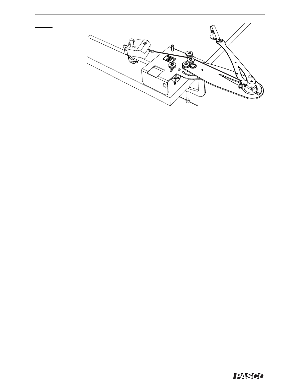
Part B
Set-up
1.
Clamp the arm
model horizon-
tally as illus-
trated.
2.
Clamp the rod to the base of
the model as illustrated. Use the
sensor clamp and stud to attach the force
sensor to the rod.
3.
Attach an elastic cord as illustrated. Adjust the length of
the cord so that the cord is under slight tension when the elbow is fully flexed.
4.
Connect the force sensor to your interface.
5.
Set the sampling rate of the force sensor to 200 Hz.
6.
Prepare graphs to plot elbow angle, angular velocity (in rad/s), and biceps force
versus time.
7.
Set up the software so that you can see the angle reading as you take data.
Procedure
1.
Start data collection.
2.
Pull the forearm and hold it at 79°.
3.
Release the forearm and let it move freely as the elastic cord contracts.
4.
Stop data collection.
Analysis
For this analysis we will look at the angular acceleration when the elbow angle is
about 90°. The rotational inertia is (approximately)
, where r = 0.045 m is
the distance from the elbow to the insertion point, F is the biceps force, and
α is the
rotational acceleration.
1.
On the graph of angle versus time, identify the time span during which the elbow
rotates from 80° to 100°.
2.
Over the same time span, find the average force, F.
3.
Over the same time span, fit a line to the angular velocity versus time plot. The
slope of this line is
α.
4.
Use these values of F and
α to determine the rotational inertia.
I
rF
α
⁄
=