Attaching cords to the arm model, How angles are measured – PASCO ME-6807A Human Arm Model User Manual
Page 6
®
H u m a n A r m M o d e l
A tt a c h i n g C o r d s t o t h e A r m M o d e l
6
Attaching Cords to the
Arm Model
Cords are used to represent the muscles of
the upper arm. Depending on how you will
use the model, you can attach one or two
cords, use standard cords or elastic cords,
and run the cords over and under the pulleys
in various ways.
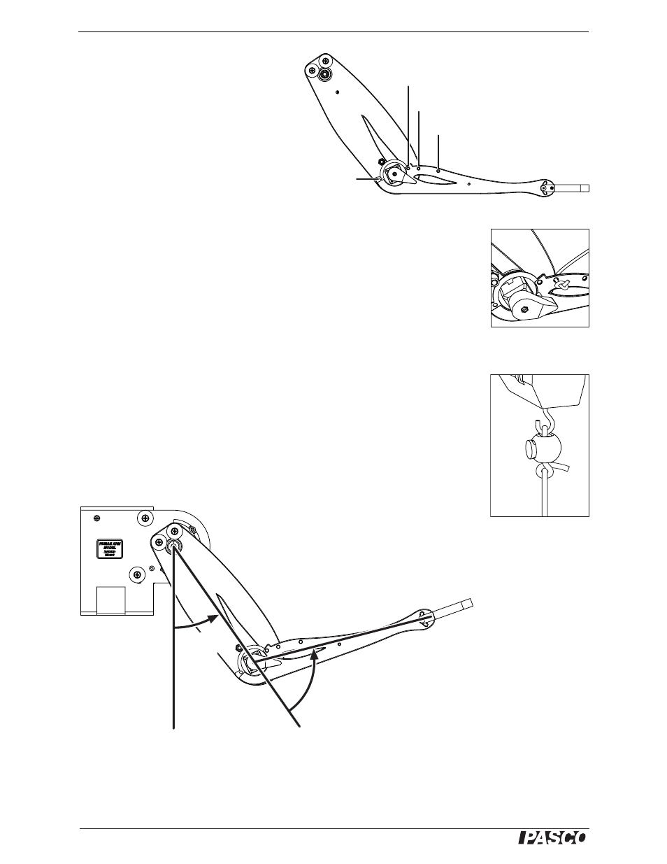
The biceps cord can be attached at the stan-
dard muscle insertion point, representing a
human arm, or at one of the other two insertion points, for more or less leverage (Fig-
ure 5).
1.
Tie a knot near the end of a cord and thread the other end through one of the
insertion point holes. Pull the cord through until the knot stops against the hole
(Figure 6).
2.
Run the cord over and under the pulleys in the desired configuration. (For exam-
ples, see the experiments and demonstrations starting on page 9.)
3.
Use one of the include cord locks to make a loop in the free end of the cord. Place
the loop over a post or a force sensor hook. Adjust the length of the cord. Push
the cord lock against the post or hook and tie a knot against the cord lock to pre-
vent it from slipping (Figure 7).
How Angles are Measured
The angle sensor determines the shoulder and elbow angles from the resistance of the
potentiometers built into the joints. Figure 8 shows how the angles are measured.
Figure 8: How angles are measured
Figure 5: Muscle insertion points
inner biceps insertion point
standard biceps insertion point
outer biceps insertion point
triceps
insertion
point
Figure 6: Cord attached
to insertion point
Figure 7: Cord attached
to force sensor with
cord lock
shoulder
angle
elbow
angle