Experiment 1: angular acceleration - 1 – PASCO ME-9341 INTRODUCTORY ROTATIONAL APPARATUS User Manual
Page 13
9
012-03051F
Introductory Rotational Apparatus
Experiment 1: Angular Acceleration - 1
EQUIPMENT NEEDED:
- Introductory Rotational Apparatus with auxiliary platter, ring, steel bar, and bubble level
- Smart Pulley with table clamp and software
- 2.5-newton spring balance
- Apple II or IBM PC or compatible computer
- thread
When a force causes an object to rotate, the angular acceleration of the object depends upon
four factors: (1) the magnitude of the force, (2) the direction of the force, (3) the point on
the object at which the force is applied, and (4) the rotational inertia of the object. In this
lab you will investigate the quantitative relationship between these four factors and the
angular acceleration of a rotating system. A spring balance will be used to apply the force.
Procedure
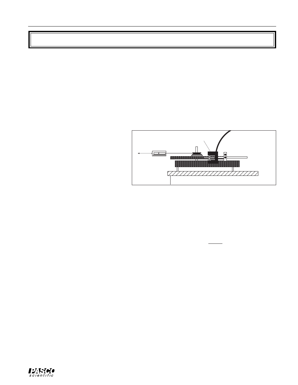
➀ Set up the apparatus as shown in
Figure 1.1. Place the main platter on
the shaft so that the step pulley is on
top. Use the bubble level to level the
apparatus.
➁ Insert the Smart Pulley Timer soft-
ware disk into your computer disk
drive and start up the computer.
[Note: Please refer to the Smart
Pulley Timer manual.]
➂ Attach a 2-3 meter piece of thread to your spring balance. Attach the other end to the step
pulley and wind it up on the smallest of the three spindles. Hold the Smart Pulley lightly
against the edge of the platter. If the LED on the Smart Pulley photogate is OFF, rotate the
platter slightly until it comes ON.
➃ Now select MOTION TIMER from the main menu. Pull the thread with a constant force of
0.4 newton while the Smart Pulley monitors the motion of the platter. Just before the thread
runs out, push
➄ When the computer finishes calculating the times, examine the data table. If you think your
run was good, press
program. You will be asked to identify the type of device used to interrupt the photogate.
See Option a on page 4. Select ROTATIONAL APPARATUS or OTHER (ANGULAR
MEASUREMENT) depending on which style of Smart Pulley you are using. Then select
VELOCITY VS TIME for a velocity-time graph.
➅ For the graph style, select STATISTICS, so the computer will do a statistical analysis of
your data (press the S-key, then press the space bar so a check appears to the left of your
selection). When the graph is constructed, there will be three sets of numbers at the top.
"M" is the slope of the graph, which is the angular acceleration of the platter in rad/sec
2
.
➆ In Table 1.1, record the angular acceleration, the force you applied with the spring balance,
and the radius of the spindle of the step pulley around which the thread was wrapped.
➇ Go back to step 4 and repeat the experiment using the same force, but use the next largest
spindle on the step pulley. Repeat again using the largest spindle.
➈ Go back to step 4, use the smallest spindle again, but now use 0.8, 1.2, 1.6 and 2.0 newtons
of force.
Figure 1.1 Equipment Setup
Pull with
constant
force.
Smart Pulley