Experiment 4: snell’s law, Purpose, Theory – PASCO OS-8459 Beginning Optics System User Manual
Page 13: Procedure
®
M o d e l N o . O S - 8 4 5 9
E x p e r i m e n t 4 : S n e l l ’ s L a w
13
Experiment 4: Snell’s Law
Purpose
The purpose of this experiment is to determine the index
of refraction of the acrylic rhombus. For rays entering
the rhombus, you will measure the angles of incidence
and refraction and use Snell’s Law to calculate the index
of refraction.
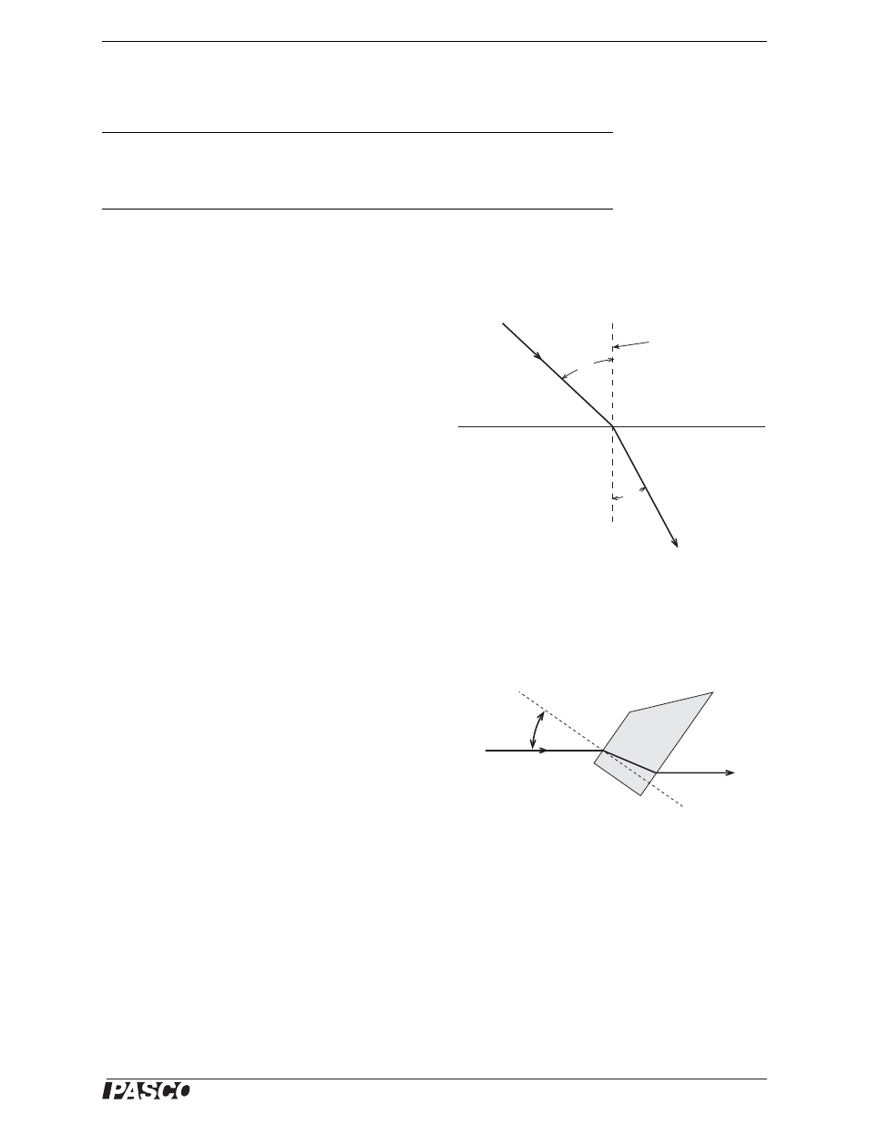
Theory
For light crossing the boundary between two transparent
materials, Snell’s Law states
n
1
sin
θ
1
= n
2
sin
θ
2
where
θ
1
is the angle of incidence,
θ
2
is the angle of
refraction, and n
1
and n
2
are the respective indices of
refraction of the materials (see Figure 4.1).
Procedure
1.
Place the light source in ray-box mode on a sheet of
white paper. Turn the wheel to select a single ray.
2.
Place the rhombus on the paper and position it so
the ray passes through the parallel sides as shown in
Figure 4.2.
3.
Mark the position of the parallel surfaces of the
rhombus and trace the incident and transmitted rays.
Indicate the incoming and the outgoing rays with arrows in the appropriate direc-
tions. Carefully mark where the rays enter and leave the rhombus.
4.
Remove the rhombus and draw a line on the paper connecting the points where
the rays entered and left the rhombus. This line represents the ray inside the
rhombus.
5.
Choose either the point where the ray enters the rhombus or the point where the
ray leaves the rhombus. At this point, draw the normal to the surface.
6.
Measure the angle of incidence (
θ
i
) and the angle of refraction with a protractor.
Both of these angles should be measured from the normal. Record the angles in
the first row of Table 4.1.
Required Equipment from Beginning Optics System
Light Source
Rhombus from Ray Optics Kit
Other Required Equipment
Protractor
White paper
Normal to surface
Surface
Refracted ray
(n
1
>
n
2
)
Incident ray
n
1
q
1
q
2
n
2
Figure 4.1
q
i
Incident ray
Figure 4.2