PASCO CI-6538 Rotary Motion Sensor User Manual
Page 26
®
Model No. CI-6538
Rotary Motion Sensor
25
Measurements for the Experiment Method
a) Finding the Acceleration of the Ring and Disk
1.
Open DataStudio and select "Create Experiment."
2.
In the Sensors list of the Experiment Setup window, click and drag a RMS
Sensor icon to the first of the two consecutive digital ports that the RMS is
plugged into on the interface.
3.
Double click the RMS icon in Experiment Setup window to open the
Sensor Properties dialog box.
4.
In the Measurement tab of the Sensor Properties dialog, select "Angular
Velocity (rad/s)."
5.
In the Rotary Motion Sensor tab of the Sensor Properties dialog, ensure
that the Divisions/Rotation radio button is in the 360 position, and select
the appropriate pulley in the Linear Calibration pop-up menu; click OK.
6.
Put the 50 g mass on the Mass Hanger and wind up the thread. Click on
the Start button; then release the 3-step Pulley, allowing the mass to fall.
7.
Click the Stop button to end the data collection.
HINT: Click the stop button before the mass reaches the floor or the end of
the thread to avoid erroneous data.
8.
In the Graph Display window, click on the Statistics button; then select
the linear curve fit from the pop-up menu. The slope of the linear fit
represents the angular acceleration ( ) and should be entered in Table 2.2.
b) Measure the Radius
1.
Using calipers, measure the diameter of the pulley about which the thread is
wrapped and calculate the radius. Record in Table 2.2.
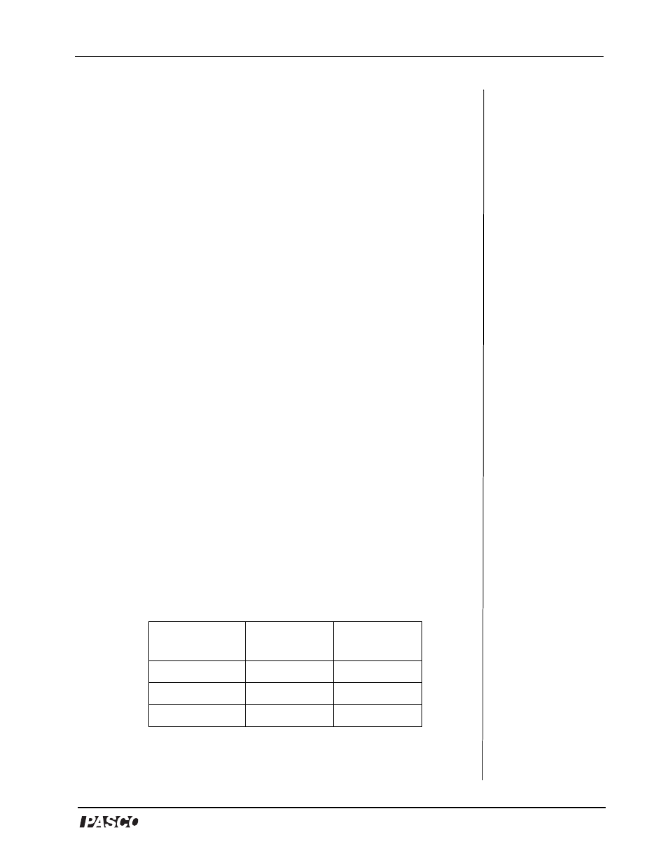
α
Parameter
Ring and Disk
Combined
Disk Alone
Hanging mass
Slope
Radius of pulley
Table 2.2: Experimental Rotational Inertia Data