PASCO CI-6538 Rotary Motion Sensor User Manual
Page 19
Rotary Motion Sensor
Model No. CI-6538
18
®
(see Figure 1.1). Solving for the tension in the thread gives:
After the angular acceleration of the mass (m) is measured, the torque and the
linear acceleration can be obtained for the calculation of the rotational inertia.
Experiment Setup
1.
Attach a mass on each end
of the rod (part of the Mini-
Rotational Accessory)
equidistant from the rod
center. You may choose
any radius you wish.
2.
Tie one end of the string to
the Mass Hanger and the
other end to one of the
levels of the 3-step Pulley
on the RMS.
3.
Mount the thin rod to the
pulley on the Rotary
Motion Sensor. Please
note the orientation of the
3-step Pulley.
4.
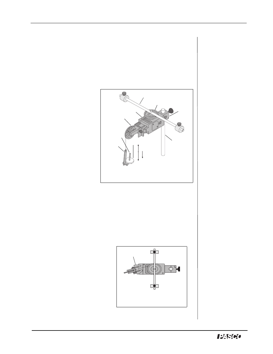
Mount the RMS to a support rod and connect it to a computer. Make sure
that the support rod does not interfere with the rotation of the accessory
rod. See Figure 1.1.
5.
Mount the clamp-on Super Pulley to the Rotary Motion Sensor.
6.
Drape the string over the Super Pulley such that the string is in the groove
of the pulley and the Mass Hanger hangs freely (see Figure 1.1)
.
Note: The clamp-on Super Pulley
must be adjusted at an angle, so that
the thread runs in a line tangent to
the point where it leaves the 3-step
Pulley and straight down the
middle of the groove on the clamp-
on Super Pulley (Figure 1.2).
7.
Adjust the Super Pulley height
so that the thread is level with
the 3-step pulley.
T
m g
a
–
(
)
=
T
mg
a
and Free Body Diagram
Figure 1.1: Rotary Motion Sensor
rod and masses
3-step Pulley
Mass hangar
mass
string
support rod
RMS
rod
clamp
clamp-on
Super Pulley
Figure 1.2: Super
Pulley Position
Super Pulley