PASCO CI-6538 Rotary Motion Sensor User Manual
Page 24
®
Model No. CI-6538
Rotary Motion Sensor
23
where
α is the angular acceleration, which is equal to a/r (a = acceleration),
and
τ is the torque caused by the weight hanging from the thread that is
wrapped around the base of the apparatus.
where r is the radius of the pulley about which the thread is wound, and T is
the tension in the thread when the apparatus is rotating.
Applying Newton’s Second Law for the hanging mass, m, gives
(see Figure 2.3). Solving for the tension in the thread gives:
Once the angular acceleration is measured, the torque and the linear
acceleration can be obtained for the calculation of the torque.
Setup
1.
Mount the RMS to a support
rod and connect it to the
interface.
2.
Mount the clamp-on Super
Pulley to the Rotational
Motion Sensor.
3.
Tie one end of the string to
the Mass Hanger and the
other end to one of the
levels of the 3-step Pulley
on the RMS.
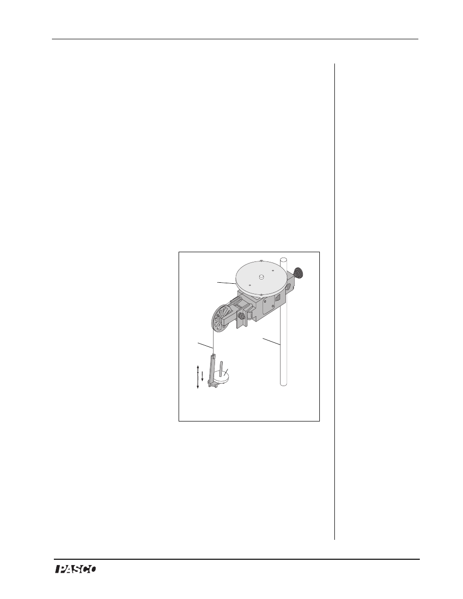
4.
Drape the string over the
Super Pulley such that the
string is in the groove of the
pulley and the Mass Hanger
hangs freely (see Figure
2.3).
NOTE: The clamp-on Super Pulley must be adjusted at an angle so the
thread runs in a line tangent to the point where it leaves the 3-step Pulley and
τ
rT
=
ΣF
mg
T
–
ma
=
=
T
m g
a
–
(
)
=
T
mg
a
Figure 2.3: Rotary Motion Sensor
and Free Body Diagram
disk
string
support
rod
Mass Hangar
and mass