Experiment 2: rotational inertia of disk and ring – PASCO CI-6538 Rotary Motion Sensor User Manual
Page 23
Rotary Motion Sensor
Model No. CI-6538
22
®
Experiment 2: Rotational Inertia of Disk
and Ring
Purpose:
The purpose of this experiment is to experimentally
find the rotational inertia of a ring and a disk and to
verify that these values correspond to the calculated
theoretical values.
Theory
Theoretically, the rotational inertia, I, of a ring about its center of mass is
given by:
where M is the mass of the ring, R
1
is the inner radius of the ring, and R
2
is
the outer radius of the ring. See Figure 2.1.
The rotational inertia of a disk about its center
of mass is given by:
where M is the mass of the disk and R is the
radius of the disk. See Figure 2.2.
To find the rotational inertia experimentally, a
known torque is applied to the object and the
resulting angular acceleration is measured.
Since
τ = Iα,
Equipment Required
ScienceWorkshop
®
750 Interface (CI-
6450 or CI-7599)
Rotary Motion Sensor (CI-6538)
Mini-Rotational Accessory (CI-6691)
Mass and Hangar Set (ME--9348)
Base and Support Rod (ME-9355)
Triple Beam Balance (SE-8723)
Paper clips (for masses <1 g)
Calipers
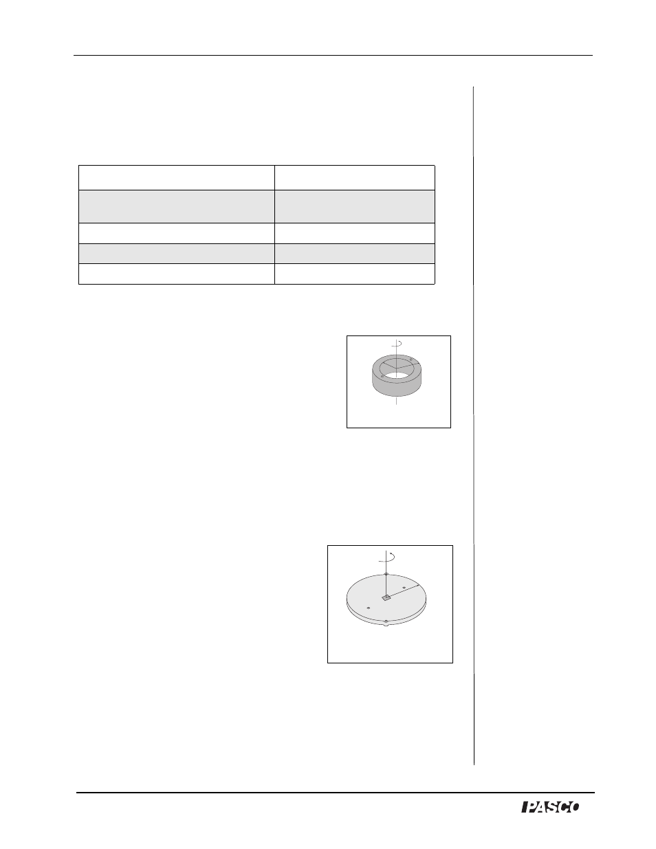
Figure 2.1: Ring
I
1
2
---M R
(
1
2
R
2
2
+
=
Figure 2.2: Disk about
center of Mass
I
1
2
---MR
2
=
I
τ
α
---
=