Pod installation, Warning relieving internal pressure, New installations – Liquid Controls POD User Manual
Page 7: Retrofit installations
Pod InstallatIon
new Installations
When ordered with the flowmeter, the POD comes factory installed on the meter and
ready for wiring. Wiring instructions begins on page 10.
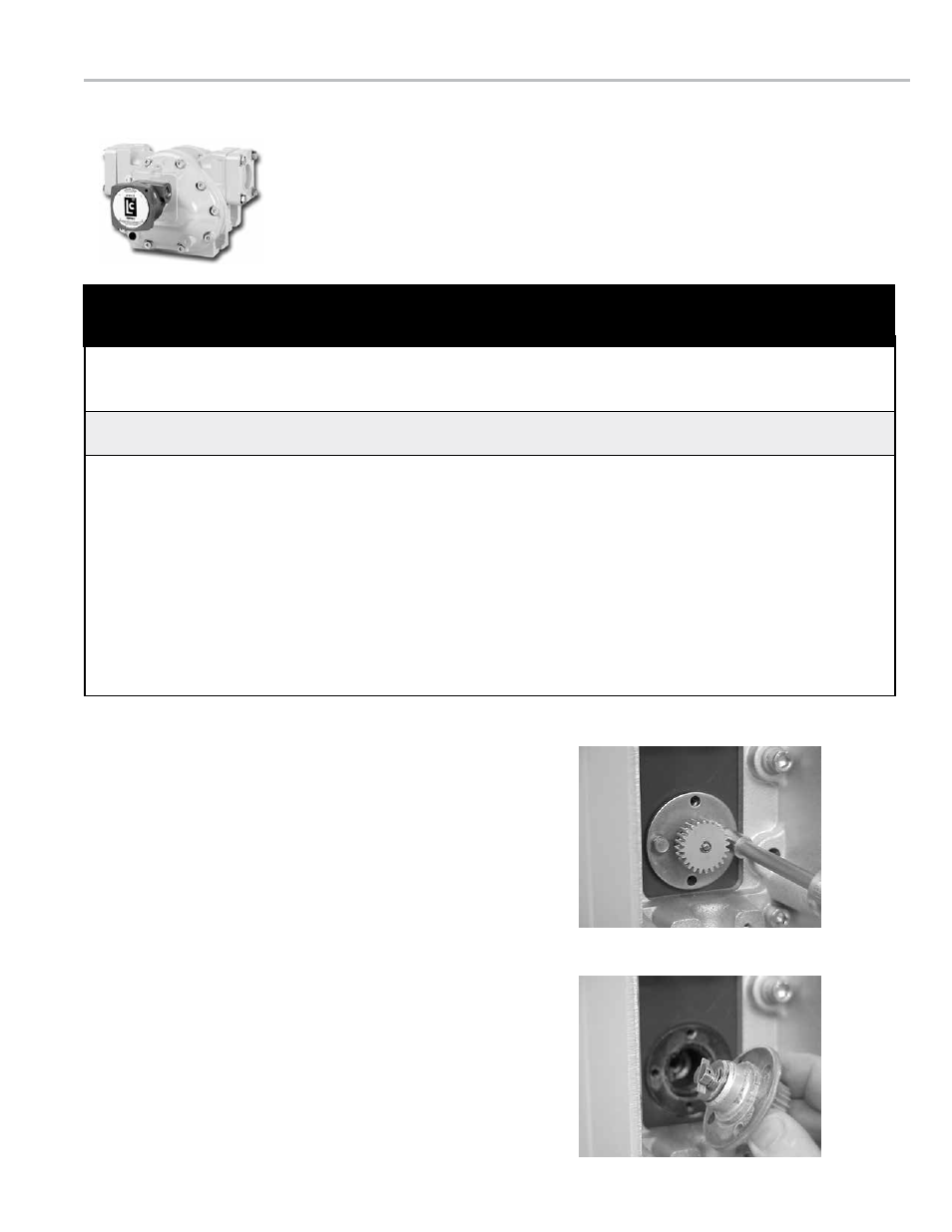
Remove Packing Gland Mounting Screws
Packing Gland Removed
Retrofit Installations
To Remove the Existing Hardware
1. Relieve the pressure from the process piping to the
meter.
2. Drain the meter by opening the meter’s drain plugs.
3. Remove the mechanical counter, adjuster, and adjuster
drive shaft from the front of the meter.
4. Some meters have a counter adapter bracket which is
bolted on. If this is the case, remove the counter bracket
by removing the bolts that hold it in place. If the counter
adapter bracket is integral to the meter, it cannot be
removed. In this case, one of four POD Pulser Extensions
will be required.
5. Remove the packing gland mounting screws. Pull the
packing gland out of the meter. If the O-Ring does not
come out with the packing gland, be sure to remove it
from the packing gland well before installing the POD.
All internal pressure must be relieved to zero pressure before disassembly or inspection of
the strainer, vapor eliminator, any valves in the system, the packing gland, and the front or
rear covers.
Relieving Internal Pressure Procedure from LPG and NH
3
meters
6. Slowly crack the fitting on top of the differential valve to
relieve product pressure in the system. Product will drain
from the meter system.
7. As product is bleeding from the differential valve, slowly
reopen and close the valve/nozzle on the discharge line.
Repeat this step until the product stops draining from the
differential valve and discharge line valve/nozzle.
8. Leave the discharge line valve/nozzle open while working
on the system.
1. Close the belly valve of the supply tank.
2. Close the valve on the vapor return line.
3. Close the manual valve in the supply line on the inlet
side of the meter. If no manual valve exists on the inlet
side, consult the truck manufacturer for procedures to
depressurize the system.
4. Slowly open the valve/nozzle at the end of the supply
line.
5. After product has bled off, close the valve/nozzle at the
end of the supply line.
Serious injury or death from fire or explosion could result in performing maintenance on an
improperly depressurized and evacuated system.
!
WarnInG
Relieving Internal Pressure
7