Pod wiring – Liquid Controls POD User Manual
Page 11
Pod WIrInG
POD Wiring
conversIon to oPen draIn outPut
As supplied by the factory, the POD has a 2.2 KΩ pull-up resistor to the positive power supply on each output
transistor. The unit can be modified in the field to provide true Open Drain (Open Collector) outputs if desired.
To modify the POD to Open Drain outputs:
1. Turn off power to the unit and remove the cover by turning it counterclockwise.
2. Loosen the three circuit board mounting screws using a Philips screwdriver. Remove the entire circuit board assembly from the
POD housing.
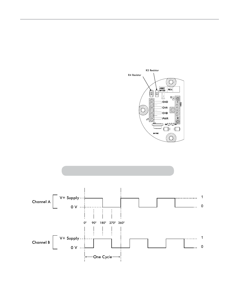
3. With a small tip soldering iron, remove the R4 and R5
resistors.
3a. Carefully, apply heat to one pad of the resistor.
3b. When the solder melts, push the resistor off the circuit
board with the tip of the soldering iron.
3c. Remove the second resistor using the same method.
4. Reassemble the unit.
POD Voltage Output clockwise rotation
Quadrature channel voltage output is 90° out of phase with Channel B
sIGnal outPut
The diagram below shows the voltage output for a clockwise rotation of the Pulse Output Device (POD) with Channel
A leading Channel B. For reverse flow applications (counterclockwise) Channel B leads Channel A.
11