Pod wiring schematics, Single channel applications, Dual channel quadrature applications – Liquid Controls POD User Manual
Page 12
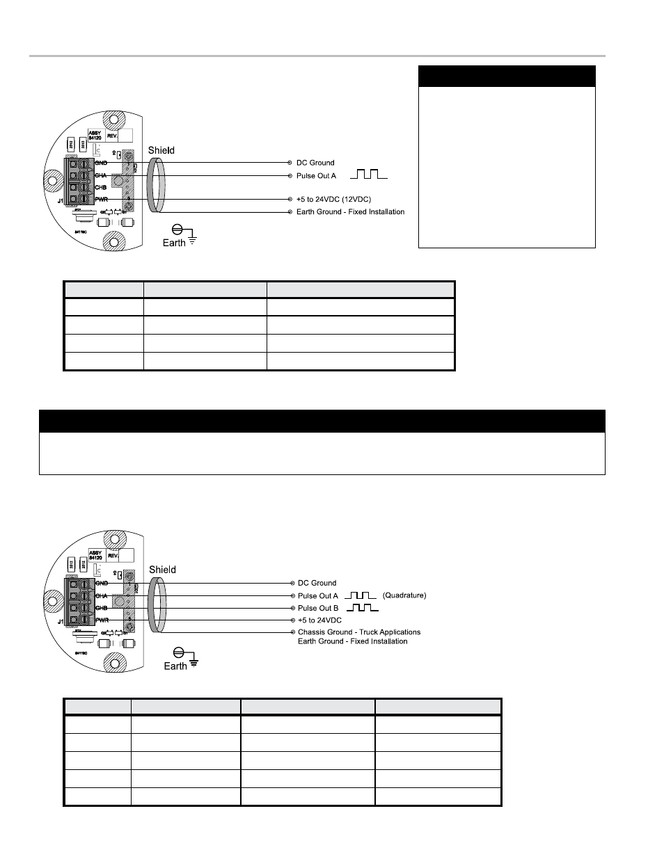
POD WIRING SCHEmATICS
For PODs with Serial Number 04-24531 and higher
Single Channel Applications
SP4000, SP3850, IT400
Description
PoD: J1 terminal
sP4000, sP3850, it400 terminal
Power
20
(12VDC)
11
(12VDC)
Channel A or B
21 or 22
9
DC Ground
23
12
Shield Wire
No Connection
Earth Ground Screw
Description
PoD: J1 terminal
lCr, lCr-ii, lCr600™: J8
lC³: J3
Power
20
(12VDC)
31
19
Channel B
21
34
17
Channel A
22
33
18
Ground
23
38
15
Shield Wire
No Connection
J6-13
(case ground)
14
(case ground)
Dual Channel Quadrature Applications
lectrocount
®
lcr
®
, LCR-II
®
, LC³, LCR 600
1. Use metallic conduit with
individual wires or use 3
conductor, 22 AWG, shielded
cable.
2. Strip 1½" off of outer sheathing.
Remove exposed shield and
drain wire and then tape.
3. Strip ¼" insulation from each
conductor and connect to the
terminal blocks.
Wiring Guide
An isolation source and overcurrent protective device rated 5A max must be installed in the power circuit. If a 5A
max isolation source and overcurrent protective device is not available, a Class 2 power source must be used.
Power Source Requirement
12