Installation – Liquid Controls MA4 Meter User Manual
Page 8
8
Installation
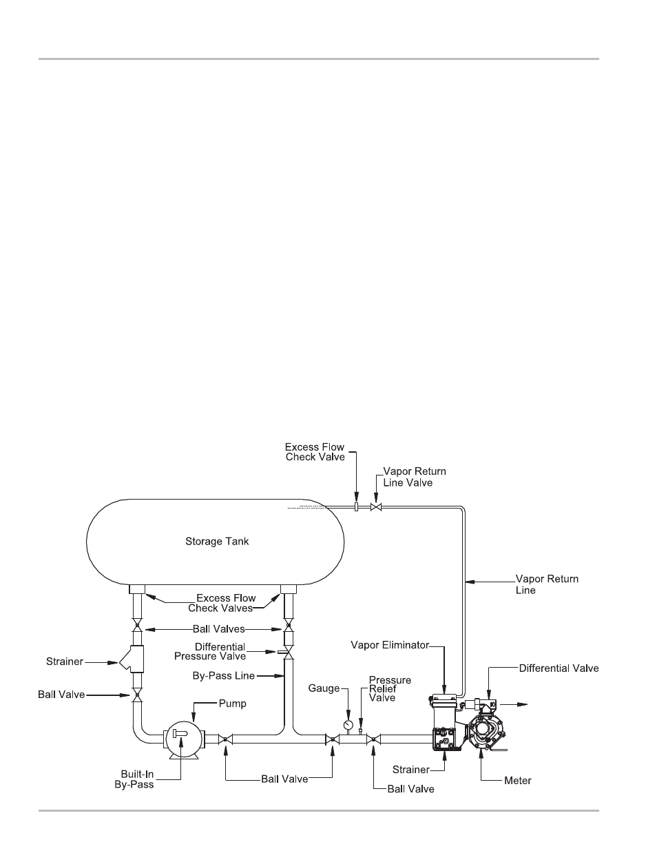
The Liquid Controls MA-4 LPG Meter combines a positive
displacement meter, differential valve, strainer, and vapor
eliminator in one assembly.
The Liquid Controls vapor eliminator employs a sleeve-
type valve that permits a “leak” flow of approximately 0.2
GPM from the vapor vent back to the supply tank. A 200-
mesh strainer is incorporated in the vapor eliminator
casting and is easily accessible by removing the strainer
cover.
The Liquid Controls differential valve incorporates a
piston-diaphragm type construction, with the piston
moving away from its seat when at least 15 psi pressure
(above product vapor pressure) is maintained at the meter
outlet. The soft seat valve assures measurement
accuracy by requiring 1) pump operation for delivery, 2)
adequate back pressure to prevent product vaporization
during measurement, and 3) blockage of flow when the
vapor eliminator release valve opens.
Theory of Operation
Meter:
Install the meter assembly in dispenser cabinet to a
secure base, using the supplied bracket on the meter
housing and the “feet” located on the strainer assembly
base. Make inlet and outlet connections at the flanged
surfaces on the strainer and differential valve,
respectively.
Vent Line:
The vent line from the meter’s vapor vent to the vapor
space on the supply tank should be 1/4 inch minimum
inside diameter tube or pipe. A shut off valve must be
installed in the vapor vent line to allow removal of the
strainer or to service the meter. The vapor release vent
line must be returned to the vapor space of the supply
tank and normally should not be made common with the
other vapor return lines or pump bypass lines. When
properly installed, this line must permit free flow in either
direction. If the valve in the vent line is closed the
meter will not function. These instructions must be
followed to maintain proper function of the differential
valve.
Meter Installation