Timing the rotor gears – Liquid Controls MA4 Meter User Manual
Page 24
24
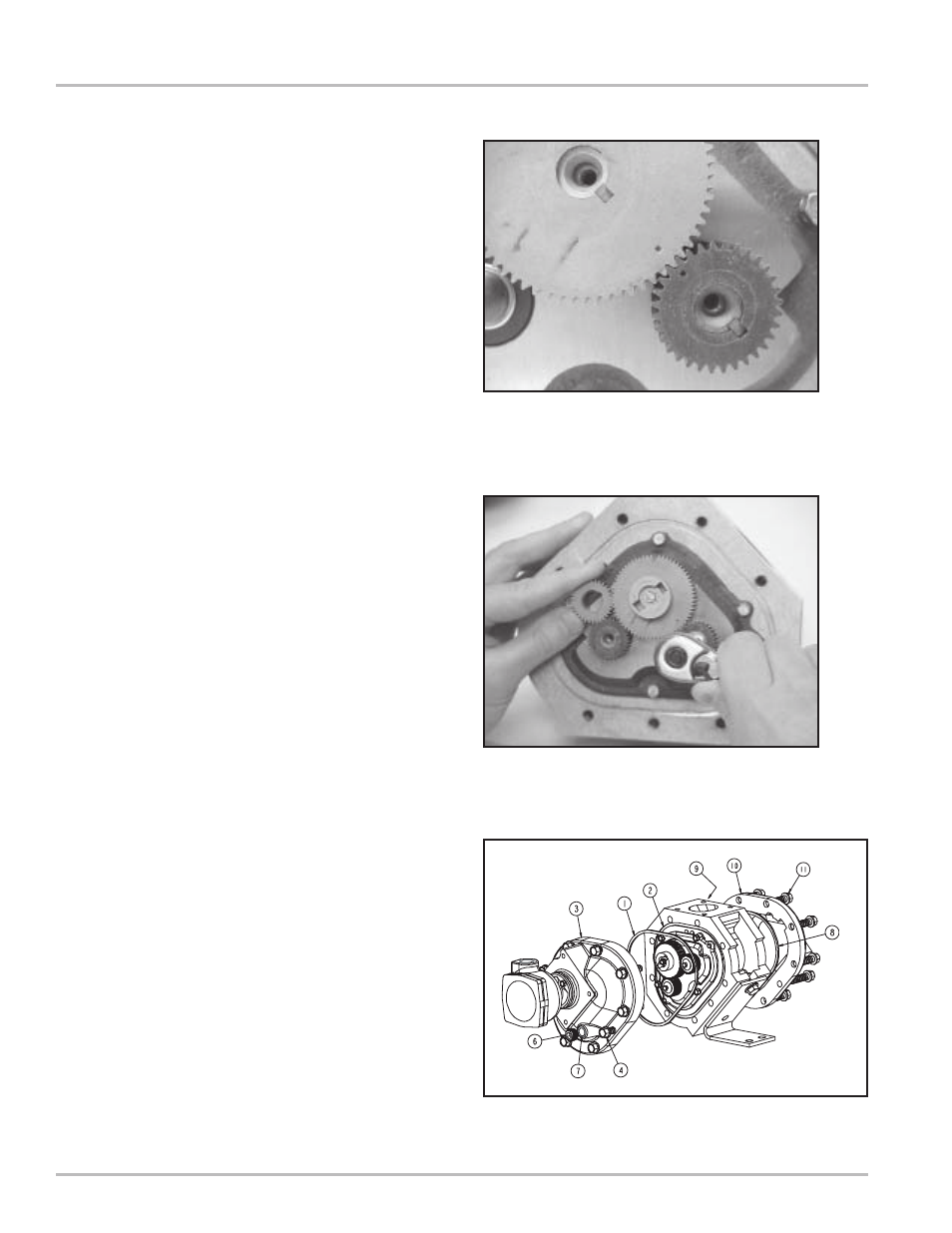
Timing the Rotor Gears
Rotor gears are timed by lining up the timing marks
(circled in illustration). The blocking rotor gear has a
tooth directly in front of its timing mark. On the
displacement rotor gears, the timing mark falls in the
space between two gear teeth. Make sure that the tooth
in front of the timing mark on the blocking rotor gear
connects with the space in front of the timing mark on
the displacement rotor gear. You may need to remove
the gears and reposition them several times on their rotor
ends in order to get the timing marks to line up correctly.
For more information, see “Troubleshooting” on Page 26.
1.
Position the spare displacement rotor gear between
the left displacement rotor gear and the blocking rotor
gear to prevent the gears from moving. Attach the
right displacement gear washer and screw using the
rotor gear wrench. Tighten the screw to the torque
specification listed in the Torque Chart.
2.
Keep the spare displacement rotor gear positioned
by the left displacement rotor gear. Attach the left
displacement gear washer and screw using the rotor
gear wrench. Tighten the screw to the torque
specification listed in the Torque Chart.
3.
Position the spare displacement rotor gear between
the right displacement rotor gear and the blocking
rotor gear. Attach the blocking rotor gear with the
packing gland driver and screw using the rotor gear
wrench. Tighten the screw to the torque specification
listed in the Torque Chart.
4.
Rotate the gears to make sure that the rotors turn
freely. Burrs, foreign material, or marred surfaces can
restrict the rotor movements. It may be necessary to
remove the gears and rotors and deburr and clean
the surfaces again.
5.
Install an O-Ring (1) into the groove (2) on the front
of the meter housing.
6.
Fasten the front cover (3) with the cover screws (4)
using the cover socket or open end/box end wrench.
7.
Install an O-Ring (8) into the groove (9) on the rear
of the meter housing. Not shown; similar to (2).
8.
Fasten the rear cover (10) with the cover screws (11)
using the cover socket or open end/box end wrench.
9.
Install POD5 Pulse Output Device.