Laurel Electronics Modbus Protocol For Series 2 Laureate Digital Panel Meters, Counters, Timers & DIN-Rail Transmitters User Manual
Page 22
- 22 -
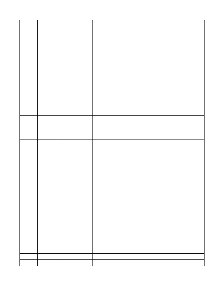
78
004E
Lockout 1
(applicable to
DPM)
0 = Enabled, 1 = Locked out
Bit 0
Offset, Lo, Hi Rd
Bit 1 Scale, Lo In, Hi In
Bit 2
Filter
Bit 3 Setup, Config, DP
Bit 4
Input Type
78
004E
Lockout 1
(applicable to
Scale Meter)
0 = Enabled, 1 = Locked out
Bit 0
Count
Bit 1 Setup, Config, DP
Bit 2
Input Type
Bit 3 Change Display Item#
Bit 4
Tare
Bit 5 Offset, Lo Rd, Hi Rd
Bit 6
Scale, Lo, Hi In
Bit 7 Filter
79
004F
Lockout 2
Bit 0
Serial Comm Config
Bit 1
Analog Out Scaling
Bit 2
Alarm Setpoint Programming
Bit 3
Alarm Config
Bit 4
Front Panel Meter Reset
Bit 5
Front Panel Function Reset
Bit 6
View Setpoints Bit 7 View Peak
81
0051
Setup 1
(not for Scale
Meter)
Bits 1:0 00 = 4-1/2 Digits, 0.1 degree
01 = Slave Remote Display
10 = 4-1/2 Dig/10, 0.01 degree
11 = 3-1/2 Digits,1 degree
81
0051
Count (applies
to Scale Meter)
Bits 3:0 0 = No auto-zero band
1= 1-count zero band
2 = 2-count zero band
3 = 3-count zero band
Etc.
9 = 9-count zero band
Bits 6:4 0 = Count by 1
1 = Count by 2
2 = Count by 5
3 = Count by 10
4 = Count by 20
5 = Count by 50
6 = Count by 100
82
0052
Analog Output
Setup (applies
to DPM)
Bit 0
0 = Source Unfiltered
1 = Filtered
Bit 1
0 = Current Output
1 = Voltage Output
Bits 2:1 00 = Current (0-20 mA) 10 = Curr. (4-20 mA)
01 = Voltage (0-10V)
11 = Voltage (±10V)
82
0052
Analog Output
Setup (applies
to Scale Meter)
Bit 0
0 = Net Value
1 = Gross Value
Bit 1
0 = Filtered
1 = Unfiltered
Bits 3:2 00 = Current (0-20 mA) 10 = Curr. (4-20 mA)
01 = Voltage (0-10V)
11 = Voltage (±10V)
87
0057
System Decimal
Point
Bits 2:0 001 = ddddd.
010 = dddd.d
011 = ddd.dd
100 = dd.ddd
101 = d.dddd
110 = .ddddd
93
005D
Start Character
Bits 7:0 ASCII Hex Character
94
005E
Stop Character
Bits 7:0 ASCII Hex Character
95
005F
Modbus Addr.
Bits 7:0 Hex value of Decimal Address from 1-255